COPYRIGHT
©
2000 CANON INC. 2000 2000 2000 2000 CANON iR5000/iR6000 REV.0 JULY 2000
CHAPTER 4 IMAGE FORMATION SYSTEM
4-46 P
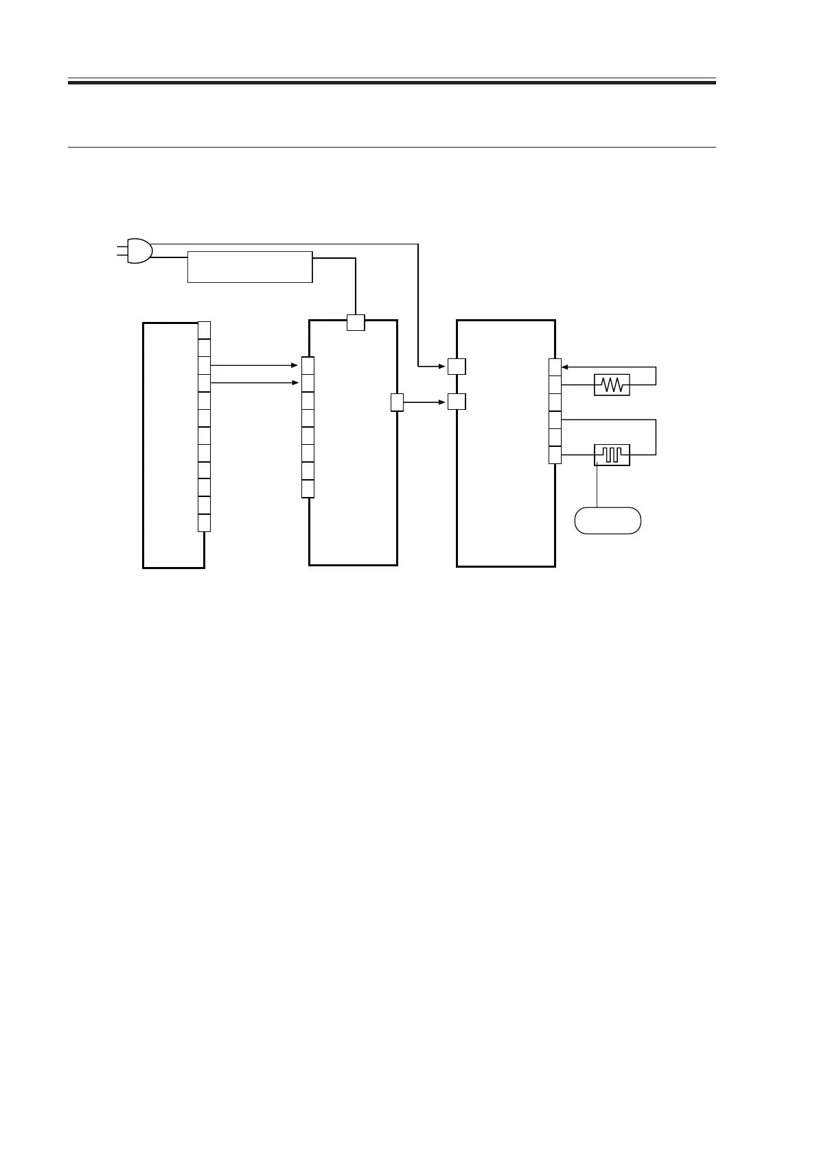
6. Controlling the Drum Heater
6.1 Outline
The system used to control the drum heater is constructed as follows:
F04-601-01
The following signals are used:
[1] drum heater drive control signal; when ‘1’, AC power is supplied to the drum heater
control PCB.
[2] thermistor temperature detection signal; feeds voltage of a level suited to the detected
temperature.
DC controller PCB
AC driver PCB
Drum heater control PCB
1
2
3
4
5
6
J2002
W1
W2
2
J2053
J102B
J2053
J2052
Environment switch
(SW3)
Controlled
to 43˚C
0V
HT-TEMP [2]
AC
DRUM HT ON [1]
Drum heater
(H3)
Thermistor
3
···
1
7
8
9
10
11
12
13
14
15
16
1
2
3
4
5
6
7
8
Download Free Service Manual at http://printer1.blogspot.com
 Loading...


