COPYRIGHT
©
2000 CANON INC. 2000 2000 2000 2000 CANON iR5000/iR6000 REV.0 JULY 2000
CHAPTER 3 LASER EXPOSURE SYSTEM
3-5 P
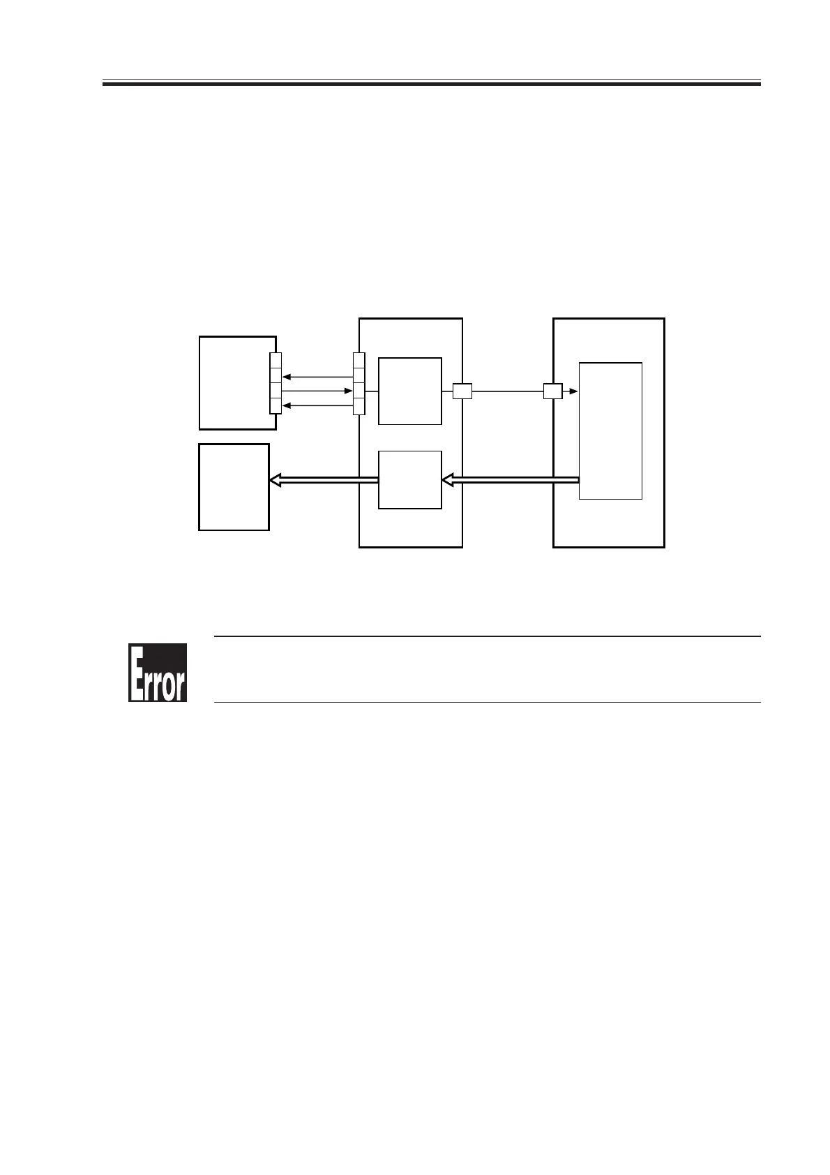
2.2 Flow of Sync Signals
[1] The BD signal goes ‘0’ when laser light is detected.
[2] A phase matching is conducted with reference to the printer, and sync signals are gener-
ated.
[3] Using the printer sync signal, image data is read from the image memory.
[4] Video signals are generated.
[5] The 2-pixel parallel signal is converted into a 1-pixel serial signal.
[6] The laser drive signal drives the laser in response to the video signals.
F03-202-01 Flow of Signals
E100
It is indicated if the BD signal is not detected within a specific period of
time after the laser has been turned on.
BD* [1]
J2701
J120
J1015
J122
J122
J117
J2502
J1015
GND
5V
VIDEO [4]
LD [6]
PSYNC[3]
4
3
2
1
A20
1
2
3
4
A21
BD PCB
Laser
driver
PCB
Serial/
parallel
conversion
[5]
Sync
signal
generation
[2]
DC controller
PCB
Control unit
Memory
control
Download Free Service Manual at http://printer1.blogspot.com
 Loading...


