COPYRIGHT
©
2000 CANON INC. 2000 2000 2000 2000 CANON iR5000/iR6000 REV.0 JULY 2000
CHAPTER 2 ORIGINAL EXPOSURE SYSTEM
2-11 R
Point of original
detection 3
Point of original
detection 4
Point of original
detection 1
Point of original
detection 2
B5
A4
B5R
A4R
B4
A3
Point of CCD original detection Point of CCD original detection
Point of original
detection 1
Point of original
detection 2
LTRR
LTR
LGL
279.4×431.8mm
(11"×17")
Original sensor Original sensor
AB-Configuration Inch-Configuration
F02-402-01
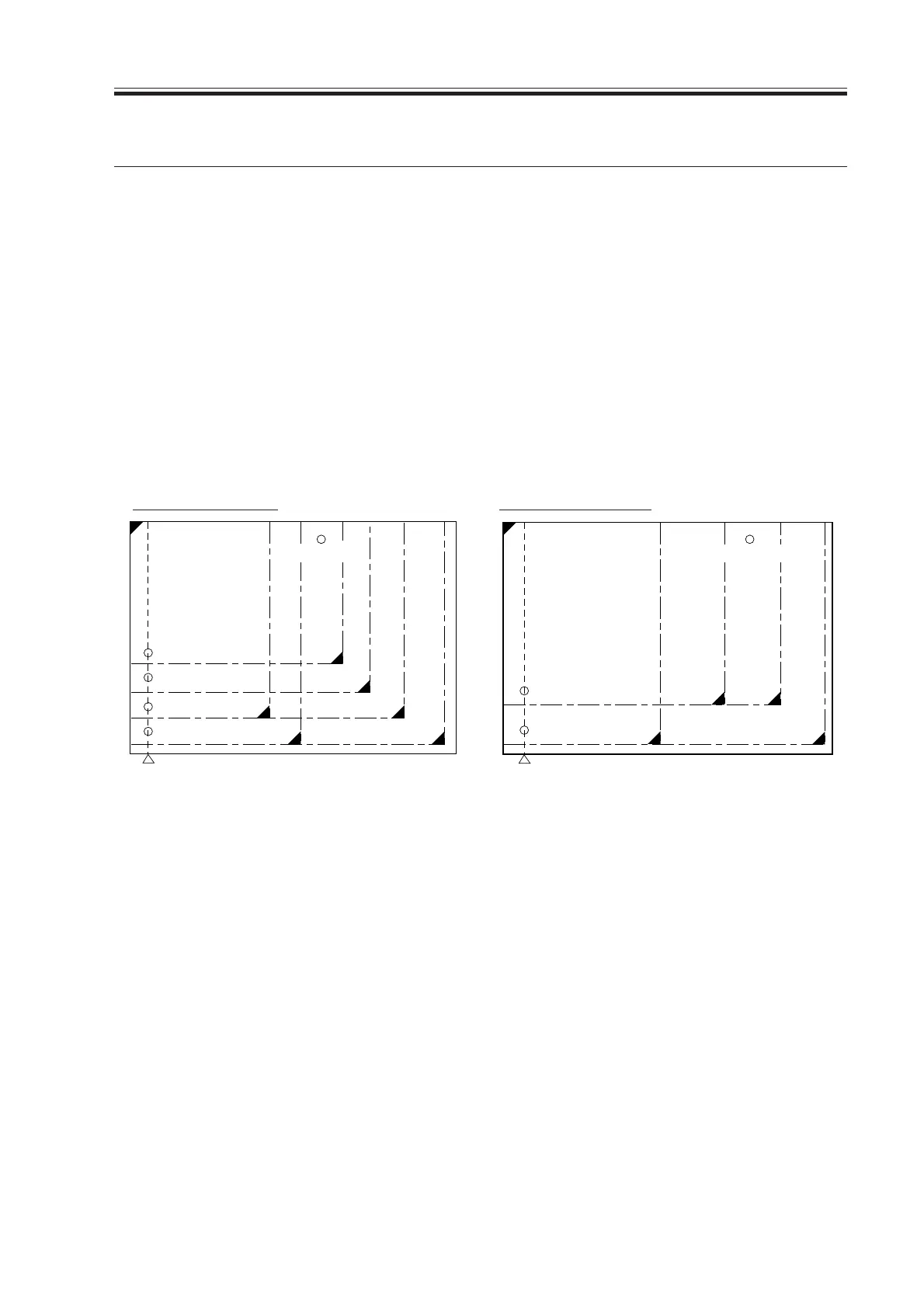
4.3 Outline of Detection
The machine identifies the size of originals in the following two steps:
[1] Detecting External Light (main scanning direction only)
While keeping the scanning lamp off, the CCD level at each point of detection in main
scanning direction is measured. A point at which external light is detected will be iden-
tified as indicating the absence of an original, enabling the identification of the width
of an original.
[2] Detecting the Sensor Output Level
The scanning lamp is turned on, and the CCD level at each point of detection in main
scanning direction is measured. In addition, the reflection type photosensor in sub
scanning direction is turned on to measure the sensor output.
The combination of these output measurements is used to identify the size of the origi-
nal. For specific movements, see the pages that follow.
4. Detecting the Size of Originals
4.1 Outline
The machine automatically identifies the size of originals based on the combination of in-
tensities measured by reflection type sensors and CCD at specific points.
• For main scanning direction, the CCD is used to take measurements (if AB, 4 points; if
Inch, 2 points).
• For sub scanning direction, a reflection type photosensor is used (1 point).
4.2 Points of Detection
For main scanning direction, the No. 1 mirror base is moved to the following points in re-
lation to the position of the original to measure the intensity at each point.
For sub scanning direction, on the other hand, measurements are taken while holding the
sensor in place at a specific point.
Download Free Service Manual at http://printer1.blogspot.com
 Loading...


