COPYRIGHT
©
2000 CANON INC. 2000 2000 2000 2000 CANON iR5000/iR6000 REV.0 JULY 2000
CHAPTER 1 GENERAL DESCRIPTION
1-25 S
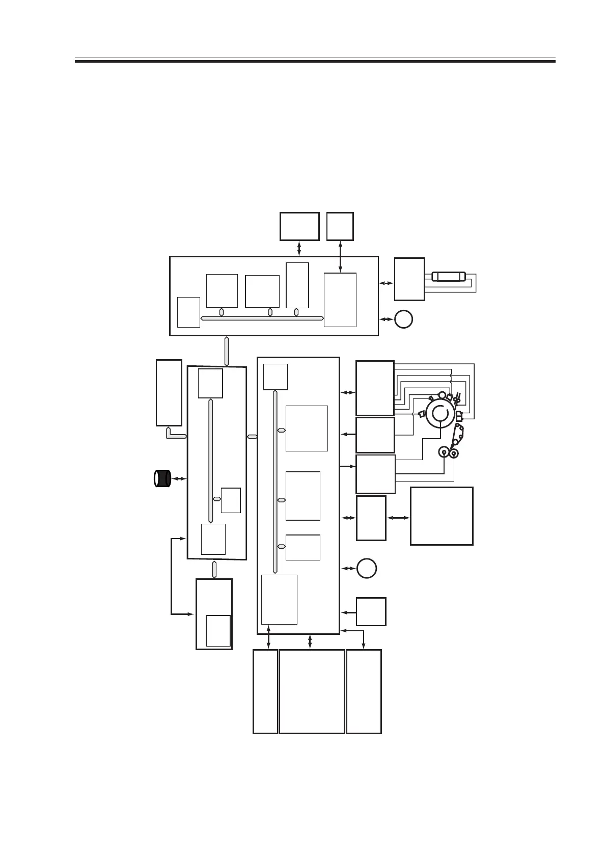
5.2 Outline of Electrical Circuitry
5.2.1 Construction of Electrical Circuitry
The machine’s major electrical mechanisms are controlled by the following PCBs:
[1] Main controller PCB. Controls the system as a whole, performs image processing.
[2] DC controller PCB. Controls the printer unit, controls finisher communications.
[3] Reader controller PCB. Controls the reader controller, controls ADF communications.
F01-502-01
DC controller PCB
HVT PCB
Potential
control
PCB
CCD/
AP
PCB
BD
PCB
ADF
Scanner
motor
Reader controller
PCB
Main controller PCB
Control
panel
Inverter
PCB
LA2
Laser scanner
motor
M15
M3
IC125
(CPU)
IC1010
(CPU)
IC121
IC122
(RAM)
(RAM)
DC load
• clutch
• solenoid
• motor
• sensor
• fan
• etc.
Cassette inside
paper level detection
PCB
Duplexing
driver PCB
DC load
• clutch
• solenoid
• motor
• sensor
• etc.
IC120
(IPC comm-
unication 2)
IC5021
(IPC com-
munication 2)
DIMM/ROM
(IC117)
IC5016
(ROM)
• Finisher
(accessory)
(HDD)
IC6501
(CPU)
(DIMM-
ROM)
IC5025
(CPU)
IC5008
IC5009
(RAM)
IC5027
(EEPROM)
IC104,105
IC109,110
IC127,130
(EEPROM)
Hard disk drive
Accessory
boards
AC driver
PCB
Download Free Service Manual at http://printer1.blogspot.com
 Loading...


