DRIVE SECTION
3-B-1
3 DIS./ASSEMBLY
DRIVE SECTION
[1] Removing and Reinstalling the Drum
Motor (M2)
Caution:
Be sure the power cord has been
unplugged from the wall outlet.
Caution: Be sure to draw the drum unit out of
the main body before removing or
reinstalling the drum drive motor. If
you fail to draw out the drum unit, the
cleaning blade may be damaged
because the drum rotates when
installing or removing the flywheel or
gear.
a. Procedure
(1) Draw the drum unit out of the main body. (See
"DRUM UNIT.")
(2) Remove the rear cover. (See "EXTERNAL SEC-
TION.")
(3) Remove the developing suction cover and right
cover (top). (See "EXTERNAL SECTION.")
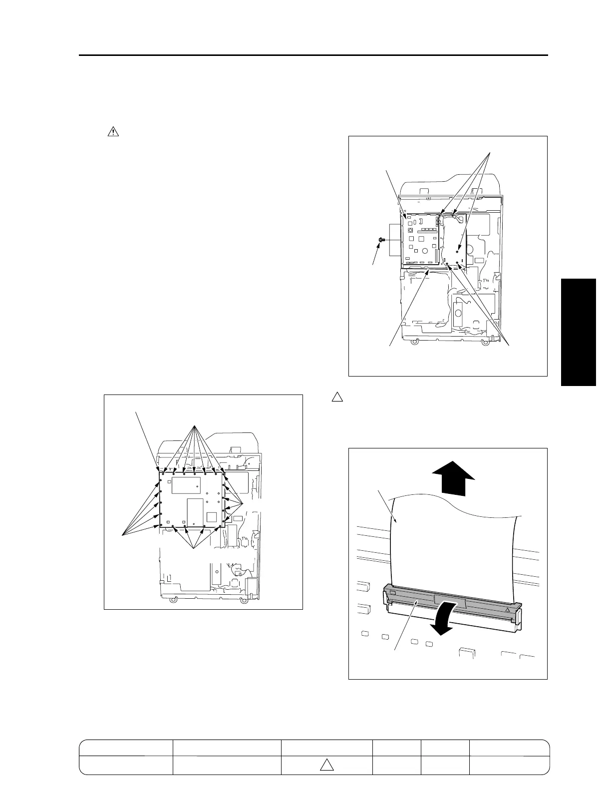
(4) Remove twenty-one screws and remove the
image control board cover.
(5) Remove five screws at the rear and three screws
on the right side and remove all connectors from
the image control board (ICB).
Caution: When removing CN110 ribbon cable,
pull and recline the lock lever front-
ward, release the lock, and then pull
out the ribbon cable.
Screws (4)
Image control board cover
Screws (7)
Screws (5)
Screws (5)
Screws (3)
Screws (2)
Screws (3)
Image control board (ICB)
Image control board mounting board
4
7272ma3002
Ribbon cable
Lock lever
MODEL MANUAL REVISED EDITION DATE PAGE METHOD
SERVICE MANUAL Dec. 2003
7155/7165/7255/7272
3-B-1 REPLACEMENT
4

 Loading...