SCANNER SECTION
2-C-8
2 UNIT EXPLANATION
[6] APS Control
The APS method used in the platen mode is dif-
ferent from that used in the ADF mode. The sig-
nal read by the APS sensor or RADF's original
size detection sensor is processed by ICB
(image control board) via SCDB (scanner drive
board).
1. Operation
a. APS detection
(1) ADF mode
The paper size is detected according to the com-
bination of ON/OFF states of PS309 (original
size/2) and PS310 (original size/1) of the RADF's
original feed tray and the resistance value of
VR301 (original paper size).
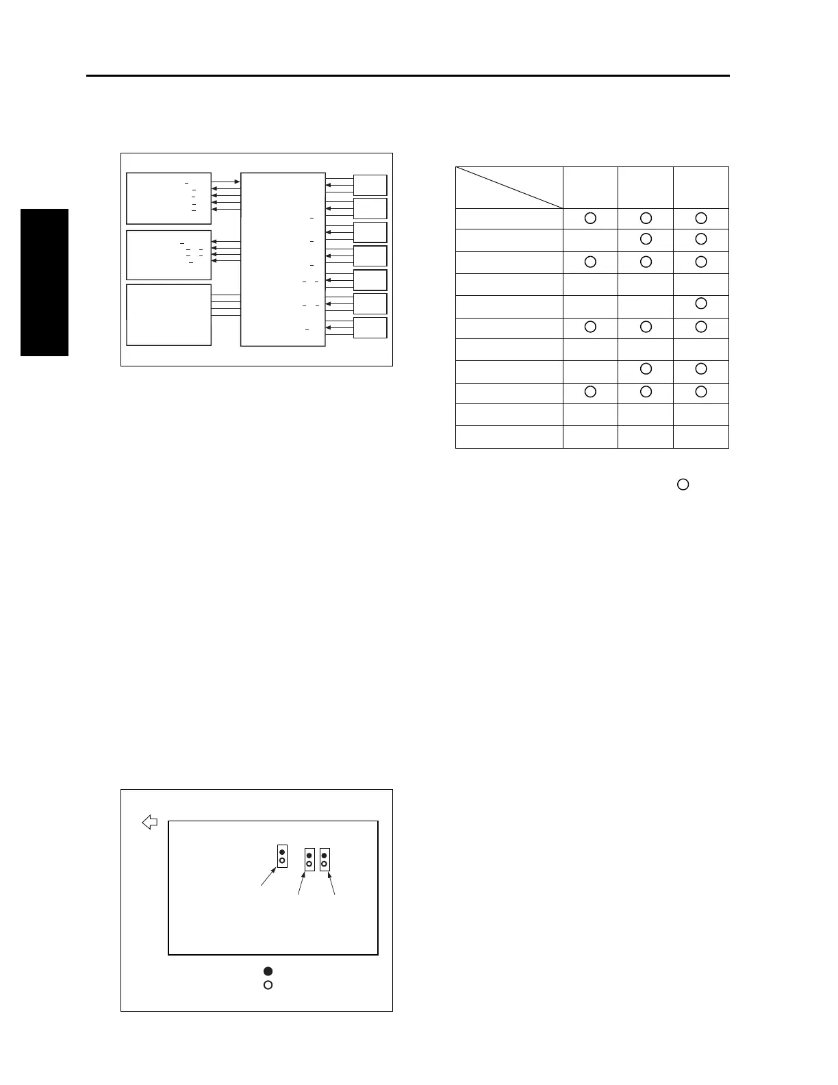
(2) Platen mode
The paper size is detected according to the com-
bination of ON/OFF states of PS63 (APS/1),
PS64 (APS/2), and PS65 (APS/3) and the signal
read by the CCD sensor. PS63 to PS65 are used
to detect the original size in the sub-scanning
direction and the CCD sensor is used to detect
the original size in the main scanning direction.
Relationships between sensors and paper sizes
are as follows:
z
ON
OFF
b. APS detection timing
The APS detection timing differs between the
platen mode and DF mode.
(1) ADF mode
When the RADF mode is selected or an original
is set on the RADF original feed tray, APS detec-
tion takes place using PS309 (original size/2),
PS310 (original size/1), and VR301 (original
size).
(2) Platen mode
When the RADF is closed and PS51 (APS tim-
ing) turns ON, L1 (exposure lamp) turns ON and
the CCD detects the reflected light to detect the
original size in the main scanning direction.
Since RADF is still open at this time, the black
level of the sky shot (outside the original) and the
white level of the original (inside the original) are
detected according to whether an original is
present. At this time, the original size in the sub-
scanning direction is detected using PS63 to
PS65 (APS/1 to APS/3). When the RADF is
closed completely and PS311 (ADF open/close)
turns ON, CCD reads the white level of the platen
cover and the black level in the original. Among
the two original sizes detected as discussed
above, the larger size is determined as the orig-
inal size in the main scanning direction.
PS51
SCDB
S.GND
APS TIM
5V
PS63
S.GND
APS.1
APS 5V
PS64
S.GND
APS.2
APS 5V
PS65
S.GND
APS.3
APS 5V
ICB
APC CONT
COVER SIG
APS.1 SIG
APS.2 SIG
APS.3 SIG
S.GND
SIZE PS L
5V
PS309
PS310
VR301
PRCB
SIZE PS L
APS TIMING
DCPS
24V1
5V2
S.GND
P.GND
SIZE PS S
SIZE ANA
S.GND
SIZE PS S
5V
A.GND
SIZE ANA
3.3V
LED
PS65
PS63
PS64
Paper exit side
Photo sensor
Sensor
Paper size
PS65 PS63 PS64
Min. size
B5R
z
B5
B4
zzz
A4R
zz
A4
A3
zzz
8.5 x 11R
z
8.5 x 11
8.5 x 14
zzz
11x 17
zzz
2-C-6

 Loading...