OTHER ADJUSTMENT
1 ADJUSTMENT
4
4
[15] FNS Adjusting the paper exit sole-
noid
(FS-110/210)
1. Tool
• Screwdriver (Phillips)
•Scale
2. Adjustment method
a. Preparation
b. Adjustment
Step Operation
1
Remove the following parts.
• Top cover /1 or option PI (if installed)
• Top cover /2
• Rear cover
2
Power on the main body, and turn on the
paper exit solenoid (SD704) using the 47
mode (code 75-31).
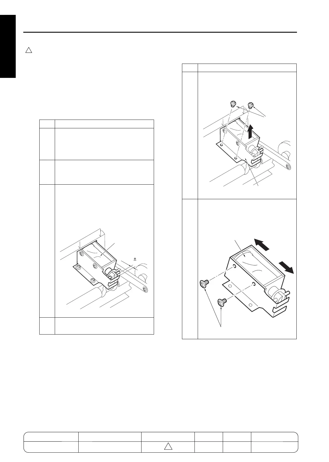
3
With the paper exit solenoid (SD704)
ON, check whether the gap between the
plunger of solenoid and the stopper of
the bracket is within the spec value.
Spec value: A=6.5
±
0.5mm
4
If the gap is out of spec, perform the fol-
lowing adjustment.
A=6.5 0.5mm
Paper exit nip SD
(SD704)
Step Operation
1
Remove two screws securing the sole-
noid bracket and remove the solenoid
together with the bracket.
2
Loosen the 2 screws holding the sole-
noid, move the solenoid to adjust its
position, and retighten the screws.
Spec value:A=6.5
±
0.5mm
Screws
Solenoid bracket
Paper exit SD
(PS704)
Screws
MODEL MANUAL REVISED EDITION DATE PAGE METHOD
SERVICE MANUAL Dec. 2003
7155/7165/7255/7272
1-116 REPLACEMENT

 Loading...