OTHER ADJUSTMENT
1 ADJUSTMENT
MODEL MANUAL REVISED EDITION DATE PAGE METHOD
SERVICE HANDBOOK May 20027155/7165
b. Adjustment
[25-1] PK Adjusting the tilt of the punch
hole position (PK-120)
2. Tool
• Screwdriver (Phillips)
•Scale
3. Adjustment method
a. Preparation
Step Operation
1
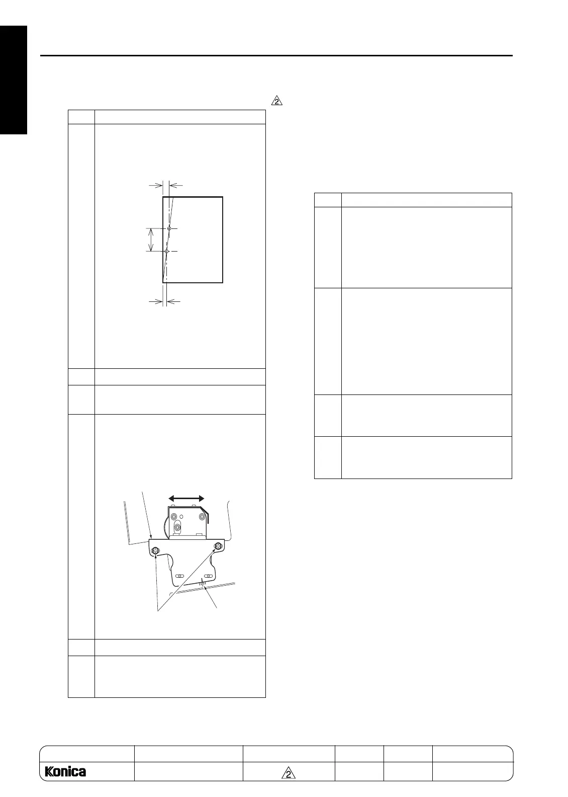
Measure the position of the sampled
punch holes to check the tilt of the posi-
tion.
Tilt of the punch hole position:
A-B (Difference in position of the two
punch holes)/C (Distance of hole pitch)
2
Open the front cover.
3
Loosen the two adjustment screws of
PK.
4
Using the mark scale as a guide, move
the punch unit horizontally by the
amount of tilt for the punch hole position.
1 scale: 0.5%
5
Retighten the screws.
6
Make a sample copy of punch mode and
recheck the tilt of the punch hole posi-
tion.
A
B
C
Mark
Adjustment side
of punch unit
Adjusting in the direction of
right and left
Adjustment screws
Step Operation
1
Check the following items:
• The finisher is connected to the main
body.
• The main body is loaded with the
paper based on the punch specifica-
tions.
2
Check the skew of output paper in
advance.
• Slide the side guide plate and the rear
guide plate for the main body's feed
tray, and align the paper loaded on the
main body's tray.
• Check the skew by using the platen
copy or adjustment mode.
3
To check the tilt of the punch hole posi-
tion, make a sample copy in the punch
mode.
4
Make three copies each in single side
copy mode and double side copy mode
with the punch mode to check the skew.
1-128
REPLACEMENT

 Loading...


