36 MODE
MODEL MANUAL REVISED EDITION DATE PAGE METHOD
SERVICE HANDBOOK Apr. 20037155/7165
1 ADJUSTMENT
1. Charging main manual adjustment
Charging main manual adjustment is inhibited in
the field.
2. Transfer manual adjustment
Default setting value must be set under the guid-
ance of Konica Technology Support Center.
3. Separation (AC) manual adjustment
Default setting value must be set under the guid-
ance of Konica Technology Support Center.
4. Separation (DC) manual adjustment
Default setting value must be set under the guid-
ance of Konica Technology Support Center.
5. Charging grid manual adjustment
See [3] "Charging Grid Voltage Adjustment".
6. Developing bias manual adjustment
Default setting value must be set under the guid-
ance of Konica Technology Support Center.
7. Transfer guide confirm
Transfer guide confirm is inhibited in the field.
8. TGR manual adjustment
TGR manual adjustment is inhibited in the field.
[3] Charging Grid Voltage Adjustment
Adjusting the charging grid voltage. Before performing
this adjustment, Check that the drum counter was reset.
Preparation: Insert the door SW jig to interlock
MS/L and interlock MS/R.
Step Operation
1
Check the adjustment value of the charg-
ing grid voltage on the durm flange.
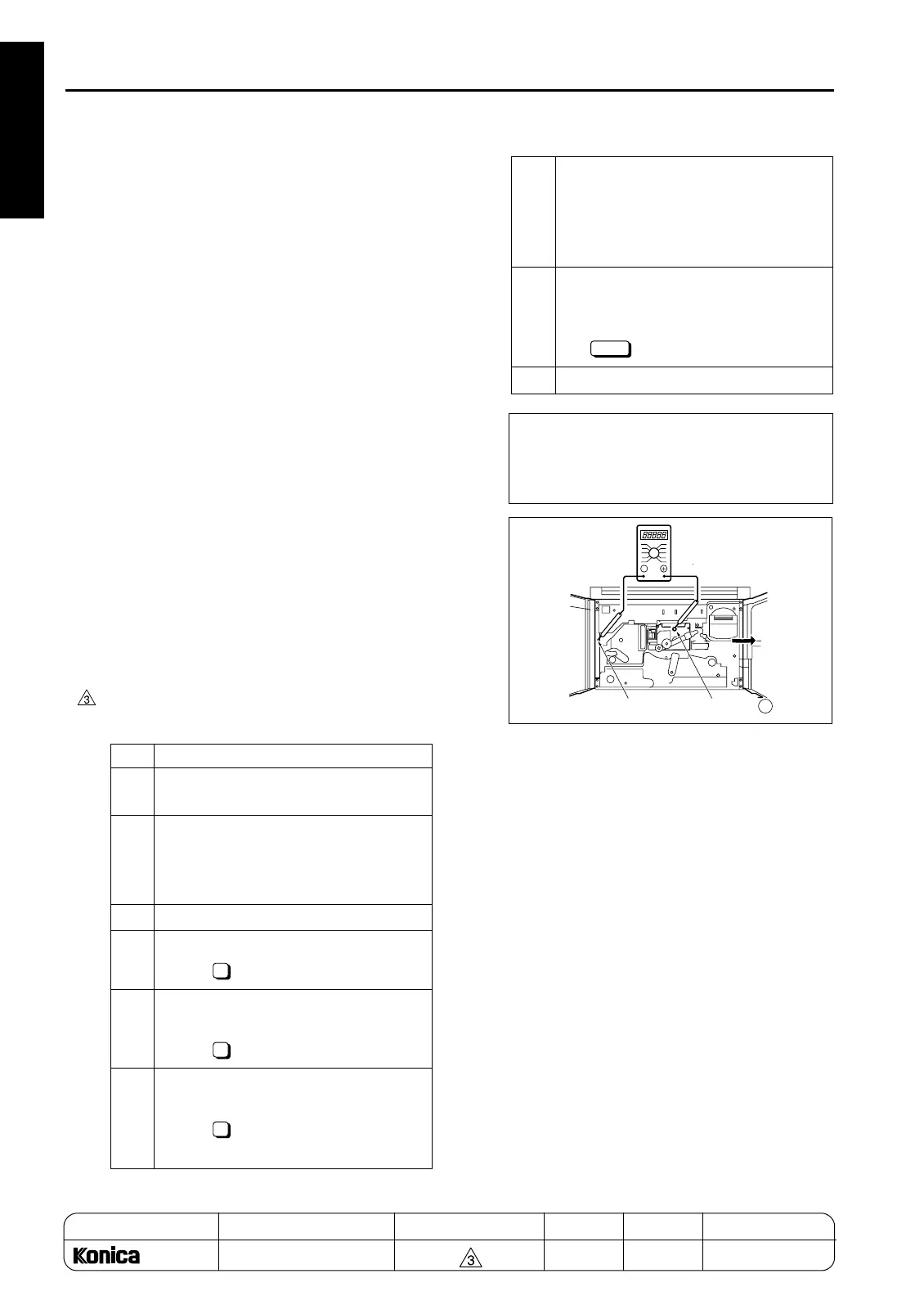
2
Connect the V tester as shown below.
+: Grid pin
-: GND (Earth)
Range: DC1000V
3
Enter the 36 mode.
4
[Adjustment mode menu Screen]
Press " Process adjustment".
5
[Process adjustment mode menu
Screen]
Press " High voltage adjustment".
6
[High voltage adjustment mode menu
Screen]
Press " HV adj. (Charging grid volt-
age)".
1
1
5
7
[HV adjustment (Charging grid volt-
age) Screen]
Press START button , and check the
voltage shown, then press CANCEL but-
ton.
8
When the voltage measured is not sat-
isfactory, change the data using the
numeric keys on the screen and press
the key.
9
Turn the SW2 (sub power) OFF.
Standard value: Specified value on the
drum flange
±
5V
Range of input: 0 to 255
1 step: 1.6V
SET
Metal frame
Grid
+
1-48
REPLACEMENT

 Loading...