SCANNER SECTION
3-C-5
3 DIS./ASSEMBLY
[4] Removing and Reinstalling the
Exposure Unit
Caution:
Be sure the power cord has been
unplugged from the wall outlet.
Caution1: When installing the exposure unit,
use the optics unit positioning jig.
Caution2: Be sure to perform image adjust-
ment after installing the exposure
unit. (See "ADJUSTMENT.")
a. Procedure
(1) Remove the right side cover (top), left side cover,
original stopper plates (left and rear), platen
glass and top cover (right, left, front center, and
rear center). (See "EXTERNAL SECTION.")
(2) Remove the operation panel. (See "EXTERNAL
SECTION.")
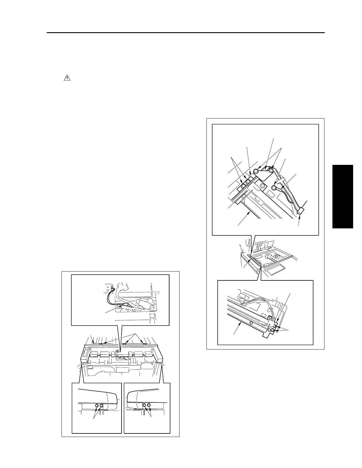
(3) Remove the relay connector (CN162).
Caution: Each relay connector consist of two
male sides and one female side. Be
sure to remove only the male side
(shown below) of the CN162 connec-
tor.
(4) Loosen the left and right screws on the operation
panel cover (top).
(5) Remove three screws and remove the operation
unit cover (top).
(6) Move the exposure unit to the notch in the main
body frame on the paper exit side.
(7) Remove two screws to detach the cord clamp
(B).
(8) Remove one screw to remove the ground termi-
nal.
(9) Disconnect the connector (CN630).
(10) Remove four screws to detach the exposure unit.
Relay connector
(CN162)
Operation panel cover
(top)
Screws (loosen)
Screws (loosen)
Screws
Cord clamp (B)
Optical wire fastener
Screws
Screws
Screw
Ground
terminal
Connector (CN630)
Exposure unit
Exposure unit
Exposure unit
Screws
Optical wire fastener
3-C-3

 Loading...