25 MODE
1 ADJUSTMENT
[7] Collecting Data
This function allows you to view various data retained
by the machine.
Reference: The above data can also be viewed
using the data collection function of
the KRDS.
1. Data that can be Viewed
In the case of the 7155/7165
Note: When bit 1 of DIP switch 30-1 is set to 0,
only collected data 1 to collected data 6
can be viewed.
In the case of the 7255/7272
Note: When bit 1 of DIP switch 30-1 is set to 0,
only collected data 1 to collected data 7
can be viewed.
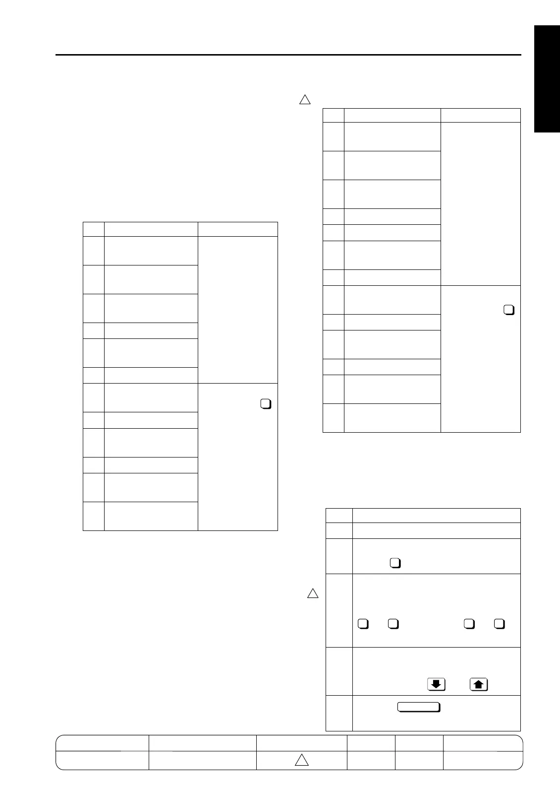
2. Viewing Collecting Data No.1 to No.6
No. Data Type Pre-operation
1
Total count of
each paper size
2
Copy count of
each paper size
3
Print count of
each paper size
4
RADF count
5
Pixel ratio of each
section
6
Pixel ratio ranking list
7
JAM data of time
series
Enter the 25
mode, select "
Software DIPSW
Setting", and set
bit 1 of address
30-1 to 1. (Note 1)
8
JAM count
9
Count of each copy
mode
10
SC count
11
JAM count of each
section
12
SC count of each sec-
tion
1
No. Data Type Pre-operation
1
Total count of each
paper size
2
Copy count of each
paper size
3
Print count of each
paper size
4
RADF count
5
Scanner count
6
Pixel ratio of each
section
7
Pixel ratio ranking list
8
JAM data of time
series
Enter the 25
mode, select "
Software DIPSW
Setting", and set
bit 1 of address
30-1 to 1. (Note 1)
9
JAM count
10
Count of each copy
mode
11
SC count
12
JAM count of each
section
13
SC count of each sec-
tion
Step Operation
1 Enter the 25 mode.
2 [Memory setting mode menu Screen]
Select " Data collection".
3 [Collecting data menu Screen]
Select the collecting data you want to
view by pressing one of numeric keys
to (7155/7165), to
(7255/7272).
4 [Individual data view Screen]
View the selected data by scrolling the
screen using the and keys.
5
Press the key to return to the
Memory setting mode menu Screen.
1
4
4
1 6 1 7
RETURN
1-23
4
MODEL MANUAL REVISED EDITION DATE PAGE METHOD
SERVICE MANUAL Dec. 2003
7155/7165/7255/7272
1-23 REPLACEMENT
4

 Loading...