DRIVE SECTION
3-B-4
3 DIS./ASSEMBLY
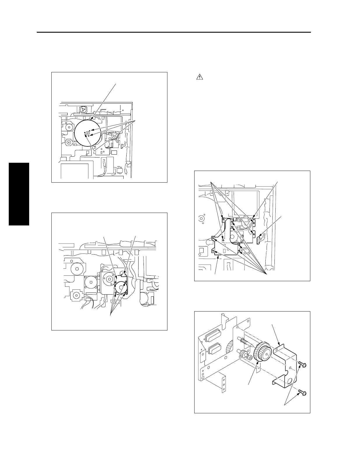
(8) Remove three screws and remove the two fly-
wheels.
(9) Remove the connector (CN301).
(10) Remove four screws and remove the drum motor
(M2).
(11) Reinstall the above parts following the removal
steps in reverse.
[2] Removing and Reinstalling the Fixing
Input Gear
Caution:
Be sure the power cord has been
unplugged from the wall outlet.
a. Procedure
(1) Open the image control bard mounting board.
(2) Remove six screws and remove the fixing motor
cover.
(3) Pull out the connector (CN304), remove four
screws to remove the fixing motor assembly.
Caution: Hold the fixing motor assembly with
your hand because it is connected to
the main body with cable.
(4) Remove two screws to remove the fixing input
gear holder.
(5) Pull out the fixing input gear from the shaft.
(6) Reinstall the above parts following the removal
steps in reverse.
Flywheels (2)
Screws (3)
Drum motor (M2)
Connector (CN301)
Screws (4)
Screws (4)
Screws (6)
Connector
(CN304)
Fixing motor assembly
Fixing motor cover
Fixing input gear holder
Fixing input gear
Screws (2)
3-B-2

 Loading...