WRITE SECTION
3-D-1
3 DIS./ASSEMBLY
WRITE SECTION
[1] Removing and Reinstalling the Write
Unit
In the case of the 7155/7165
Warning:
(1) Do not energize the write unit when it is
not in the correct position.
(2) Never remove the write unit cover and
the polygon unit cover.
(3) Never look directly into the laser beam. It
can cause blindness.
(4) Never remove the write unit for at least
two minutes after turning OFF the main
switch.
Caution:
Be sure the power cord has been
unplugged from the wall outlet.
a. Procedure
(1) Remove the left side cover. (See "EXTERNAL
SECTION.")
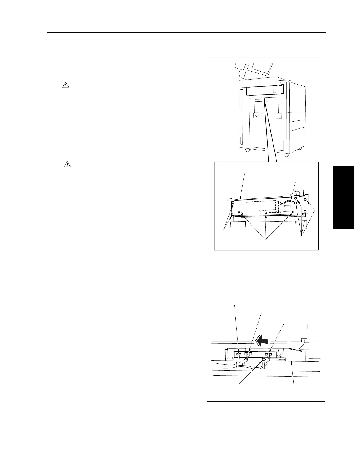
(2) Remove nine screws to detach the fan holder
assembly.
(3) Remove the relay connector (CN338).
Caution: Each relay connector consists of two
male sides and one female side. Be
sure to remove only the male side
(shown below) of the CN338 connec-
tor.
(4) Remove the three connectors (CN185, 187,
188).
(5) Loosen the screw to draw out and remove the
write unit.
(6) Reinstall the above parts following the removal
steps in reverse.
Fan holder assembly
Relay connector (CN338)
Screws
Screws
Screws
Connector (CN187)
Connector (CN185)
Connector (CN188)
Screw
Write unit

 Loading...