OTHER ADJUSTMENT
1 ADJUSTMENT
4
4
[34] FNS Adjusting the Magnets on Con-
veyance Guide Plate B (FS-111)
1. Tool
• Screwdriver (Phillips)
2. Adjustment method
a. Preparation
b. Adjustment
Step
Operation
4
Loosen the four screws holding the 2nd
stopper assembly.
5
Make adjustments by moving the front or
rear side of the 2nd stopper assembly
upward using the ticks for reference.
Skew pattern A: Move the rear side of
the 2nd stopper assembly upward.
Skew pattern B: Move the front side of
the 2nd stopper assembly upward.
6
Temporarily tighten the four screws hold
ing the 2nd stopper assembly, and put
the conveyance unit into the basis posi-
tion. Make a copy of the adjustment
chart to check for 2nd folding skew.
7
Repeat Steps 4 to 6 above until the 2nd
folding skew falls within the spec range
(2mm or less).
8
Tighten firmly the four screws on the 2nd
stopper assembly.
Step Operation
1
Open the front cover.
2
Check whether conveyance guide plate
B makes contact with the cushioning
rubber when the magnets are stuck to
conveyance guide plate A.
3
If conveyance guide plate B does not
make contact with the cushioning rub-
ber, remove the rear cover and carry out
adjustment as described below.
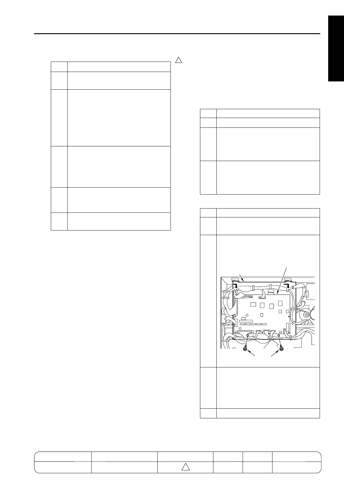
Step Operation
1
Detach all FNS CB (FNS control board)
connectors.
2
Remove the 2 set screws holding the
FNS CB in place. Remove the FNS CB
together with its bracket.
3
Loosen the 4 magnet-holding set screws
(two at the front and two at the back), and
move conveyance guide plate B all the
way in the direction indicated by the
arrow.
4
Remove the E-ring and the gear.
7272fs1015
Screws
Bracket
FNS CB (Finisher Control Board)
MODEL MANUAL REVISED EDITION DATE PAGE METHOD
SERVICE MANUAL Dec. 2003
7155/7165/7255/7272
1-137 ADDITION

 Loading...


