DRUM UNIT
3-E-1
3 DIS./ASSEMBLY
DRUM UNIT
[1] Removing and Reinstalling the Drum
Unit
Caution:
Be sure the power cord has been
unplugged from the wall outlet.
Caution1: Be sure to put a drum cover over the
removed drum unit and store the
drum unit in a dark place.
Caution2: When installing or removing the
drum unit, do not rotate it in the direc-
tion opposite to the specified one.
Rotating the drum unit in the oppo-
site direction during copy operation
could damage the cleaning blade.
Caution3: When installing or removing the
drum unit, take care not to touch the
separation claw.
Caution4: When installing a new drum, be sure
to enter mode 25 and select "Copy
Count by Parts to be Replaced" to
reset OPC drum counter.
a. Procedure
(1) Open the left and right front doors.
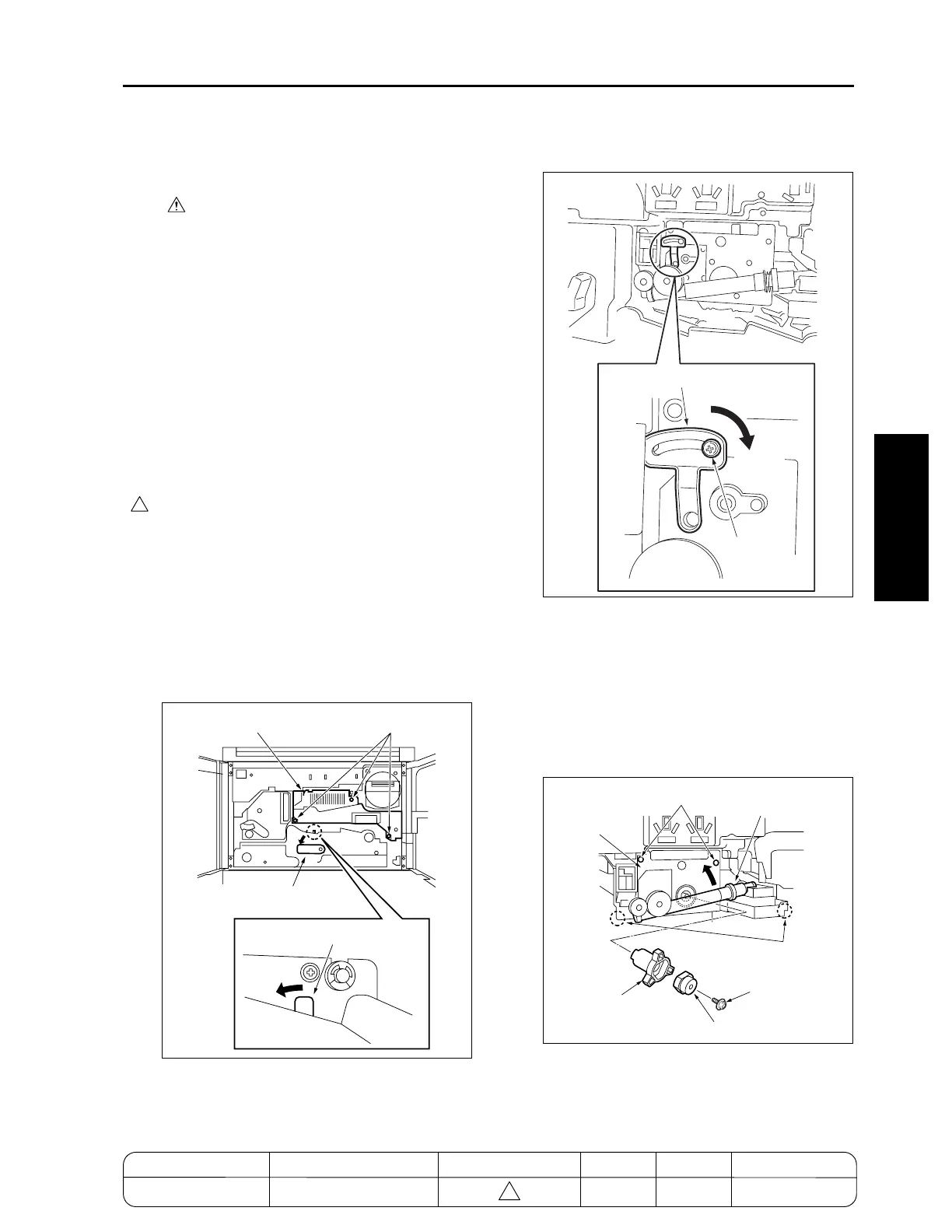
(2) While pressing the solenoid release lever on top
of the ADU rack to the left, flip the ADU rack pull-
out lever to the left.
(3) Loosen three screws to remove the drum cover.
(4) Loosen one screw and slide the blade fixing com-
ponent in the direction of the arrow until it stops
to release the crimp of the cleaning blade.
(5) Loosen the screw of the blade fixing component.
(6) Remove the two screws securing the drum unit.
(7) Release the toner supply pipe in the direction of
the arrow.
(8) Remove the screw securing the coupling to
detach the drum shaft coupling and drum cou-
pling.
(9) Hold the two sections shown in the figure and pull
out the drum unit.
(10) Reinstall the above parts following the removal
steps in reverse.
Caution: To install the coupling, see "[2] Install-
ing the Coupling."
4
Drum cover
Screws
ADU rack pullout lever
Solenoid release lever
Blade fixing component
Release
Screw
Drum unit
Screws
Screw
Toner supply pipe
Hold here
Drum coupling
Drum shaft coupling
MODEL MANUAL REVISED EDITION DATE PAGE METHOD
SERVICE MANUAL Dec. 2003
7155/7165/7255/7272
3-E-1 REPLACEMENT
4

 Loading...