SETUP
2 ISW
4
4
[6-1] Preparation when PZ is installed
When PZ is installed, to rewrite the flash ROM of
the finisher, change the wiring within PZ.
a. Procedure
(1) Power off the main body.
(2) Loosen two screws in the lower part of PZ rear
cover, remove two screws in the upper part, and
then remove the rear cover.
(3) Disconnect one connector (CN6) of PZ control
board (PZCB).
(4) Remove the finisher I/F cable assembly hanging
on the wire saddle in the lower part of PZ control
board (PZCB) and connect it to the connector
(CN6) of PZCB disconnected in the step (3).
(5) After completing the rewrite of flash ROM, dis-
connect the connector from the finisher I/F cable
assembly and reconnect the connector to CN6 of
PZ control board (PZCB).
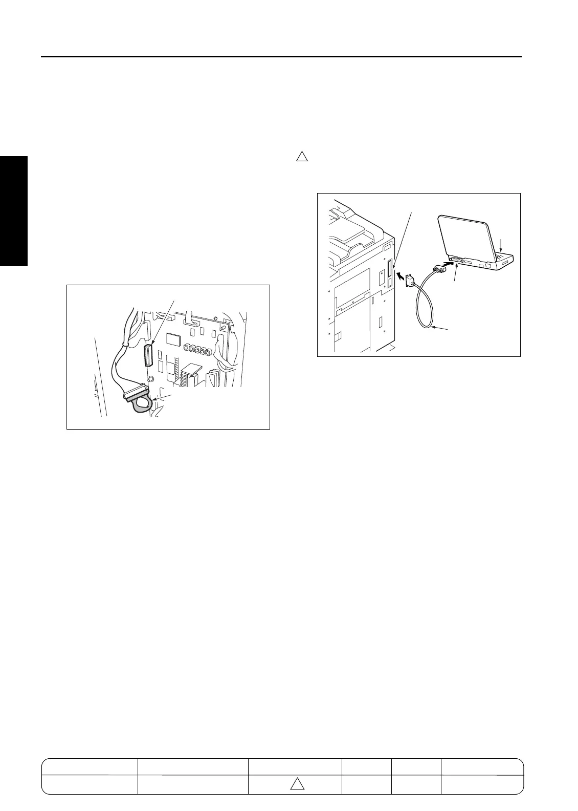
[7] Connecting to the ISW connector
The ISW connector is at the right side of the
copier.
a. Procedure
In the case of the 7155/7165
Connect the PC parallel port and the copier ISW
connector with a parallel interface cable.
CN6 (Blue)
Finisher
I/F cable assembly
(ISW)
ISW connector (36-pin)
Parallel (printer)
interface port
Parallel
interface cable
PC
MODEL MANUAL REVISED EDITION DATE PAGE METHOD
SERVICE MANUAL Dec. 2003
7155/7165/7255/7272
2-6 REPLACEMENT

 Loading...