47 MODE
1 ADJUSTMENT
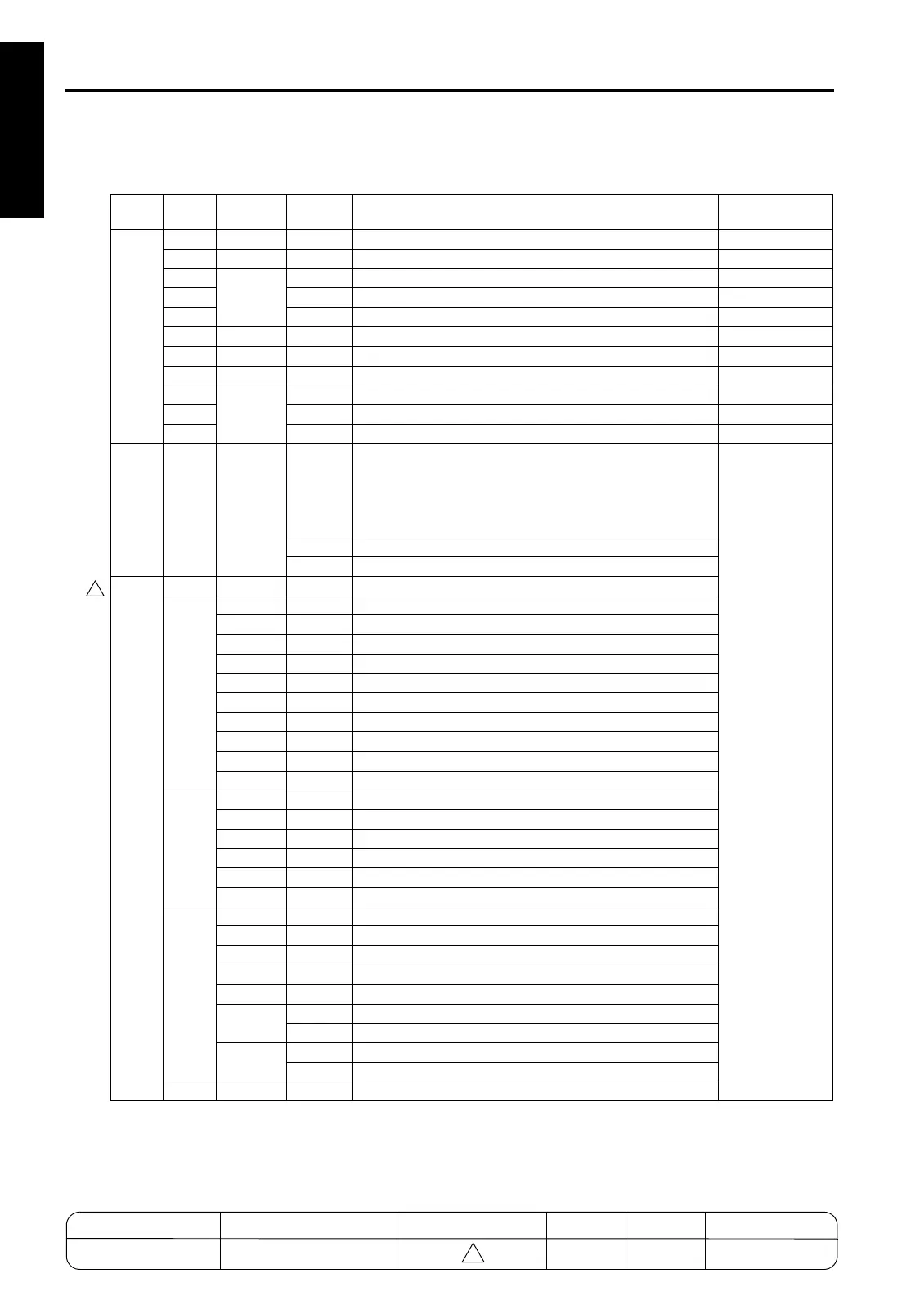
[5] Output checklist
Classi-
fication
Code Symbol
Multi
mode
Name
Cannot be set or
changed in field
Analog signal
000 L1
*1 Exposure lamp
001 M13
Toner bottle motor
002
HV
Charger
×
003
Transfer
×
004
Separation (AC+DC)
×
005
D max LED
×
006
γ
LED
×
007
Jam detection LED
×
008
HV
Transfer access guide plate
×
009
Bias
010
Toner guide roller
×
KRDS
015
1
Process adjustment related:
Clear the following data from main body and KRDS:
Copy count by size, ADF passage count, JAM count,
optional parts count, fixed parts count, count by mode, SC
count, JAM data of time series (including pointer)
2
Job memory clear
98
KRDS initialization
Paper feed
020 SD100
LCT paper feed pickup SD
021
Feed MC
MC3 1
Tray 1
MC5 2
Tray 2
MC7 3
Tray 3
MC9 4
Tray 4
MC101 5
LCT
MC11 6
Vertical conveyance CL1
MC12 7
Vertical conveyance CL2
MC15 8
Horizontal conveyance CL/L (7255/7272 only)
MC16 9
Horizontal conveyance CL/R (7255/7272 only)
022
Pre-registration CL
MC4 1
Tray 1
MC6 2
Tray 2
MC8 3
Tray 3
MC10 4
Tray 4
MC102 5
LCT
023
Tray up motor /LCT UP/DOWN motor
M16 1
Tray 1
M17 2
Tray 2
M18 3
Tray 3
M19 4
Tray 4
M100
5
LCT up
6
LCT down
M20
7
By-pass up
8
By-pass down
025 MC1
Registration MC
MODEL MANUAL REVISED EDITION DATE PAGE METHOD
SERVICE MANUAL Dec. 2003
7155/7165/7255/7272
1-92 REPLACEMENT
4
4

 Loading...