OTHER ADJUSTMENT
1 ADJUSTMENT
4
4
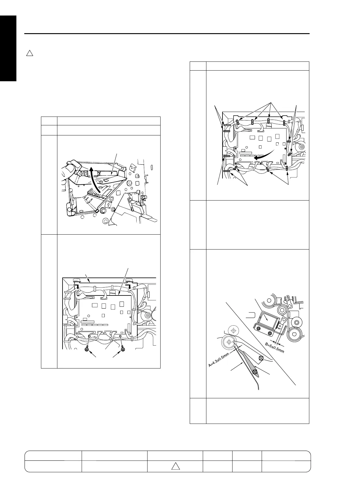
[38] FNS Adjusting the By-pass Gate
(FS-111)
1. Tool
• Screwdriver (Phillips)
•Scale
2. Adjustment method
a. Preparation
Step Operation
1
Remove the rear cover.
2
Open the front cover and the guide plate.
3
Remove the 2 set screws holding the
FNS CB in place. Remove the FNS CB
together with its bracket.
7272fs1027
Guide Plate
7272fs1028
Screws
Bracket
FNS CB (Finisher Control Board)
Step Operation
4
Remove the wirings from the clamps,
and move the FNS CB together with its
bracket.
5
With SD5 (by-pass) OFF, measure the
distance between the by-pass gate and
the guide plate, indicated by A in the
illustration.
Spec value for distance:
A = 4.3±0.5mm
6
With SD5 ON, measure the gap between
the solenoid plunger and the bracket
stopper (indicated by B in the illustra-
tion).
Spec value for gap: B = 5±0.5mm
7
If either measurement is out of spec,
carry out adjustment as described
below.
7272fs1029
Clamps
Clamps
Clamps
Clamps
Clamp
Clamps
7272fs1030
Gate
SD5 (By-pass)
Guide Plate
MODEL MANUAL REVISED EDITION DATE PAGE METHOD
SERVICE MANUAL Dec. 2003
7155/7165/7255/7272
1-142 ADDITION

 Loading...