OTHER ADJUSTMENT
1 ADJUSTMENT
4
4
b. Adjustment
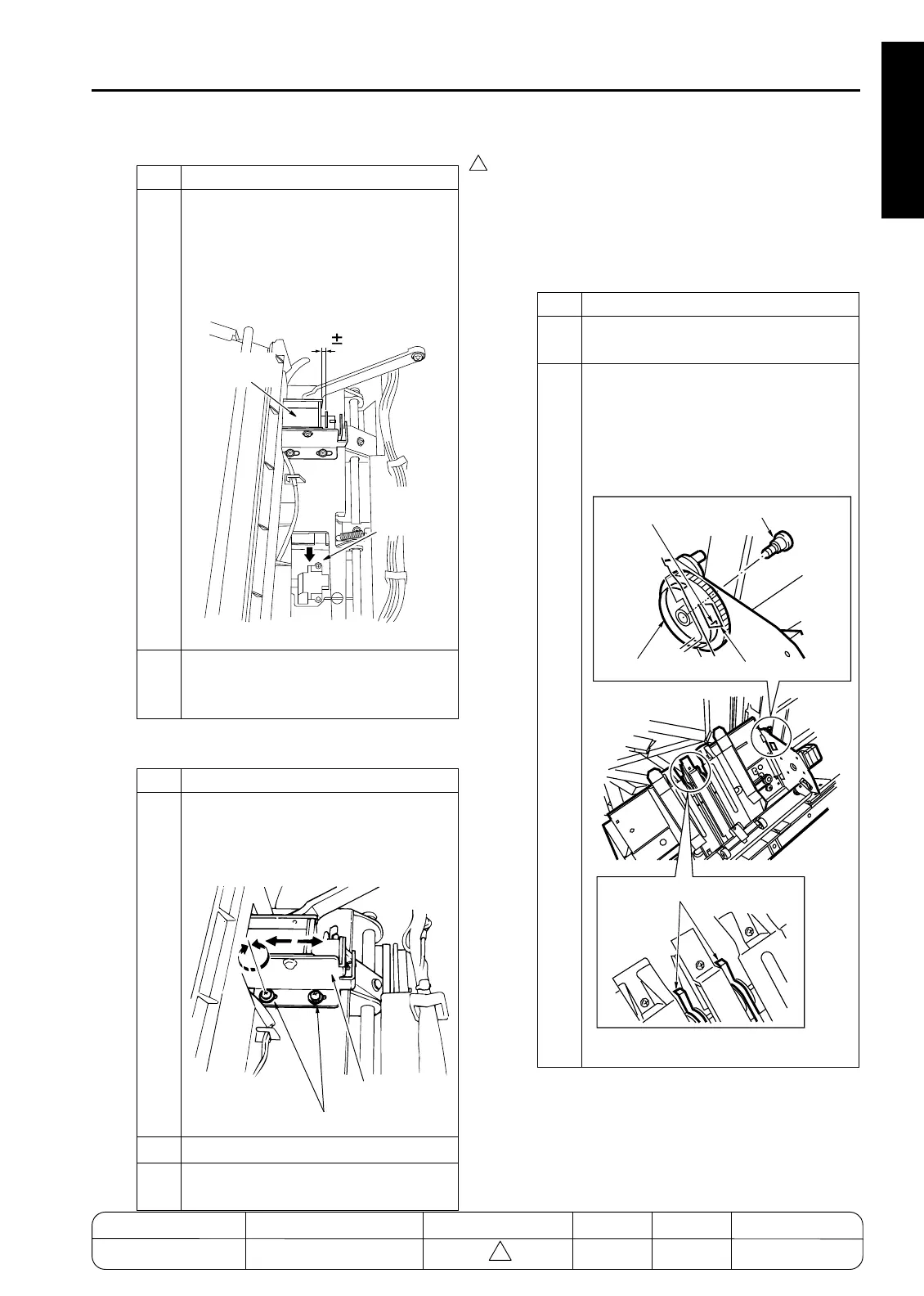
[43] FNS Adjusting the Mount Location of
the Paper Exit Arm (FS-111)
1. Tool
• Screwdriver (Phillips)
2. Adjustment method
a. Preparation
Step Operation
3
Hold down the paper exit-opening lower
guide plate with your hand so that the
paper exit roller makes contact, and
check that the remaining stroke for sole-
noid SD4 (distance B) is within spec.
Spec value: B = 2.5±0.5mm
4
If either measurement is out of spec,
carry out adjustment as described
below.
Step Operation
1
Loosen the 2 set screws holding the
solenoid bracket in place, and adjust the
position of the bracket so that distances
A and B are within spec.
2
Retighten the 2 bracket set screws.
3
Reassemble in the reverse sequence to
removal.
7272fs1040
SD4 (Paper
Exit Opening)
Paper Exit
Lower
Guide Plate
B=2.5 0.5mm
7272fs1041
Solenoid Bracket
Screws
Step Operation
1
PRemove the screw to remove the belt
detection gear.
2
When the stacker paper exit arm is at the
position shown below, secure the belt
detection gear with a screw with the
actuator end face of the belt detection
gear aligned with the bottom of the
square hole.
7272fs1042
Actuator end face
Belt detection
Bottom of square hole
Screw
Stacker paper exit arm
MODEL MANUAL REVISED EDITION DATE PAGE METHOD
SERVICE MANUAL Dec. 2003
7155/7165/7255/7272
1-147 ADDITION

 Loading...