Note
If a specific safety clearance has been set for a collision pair via the system variable
$NP_SAFETY_DIST, this has priority over the NC-specific safety clearance set in the
MD10622 $MN_COLLISION_SAFETY_DIST machine data.
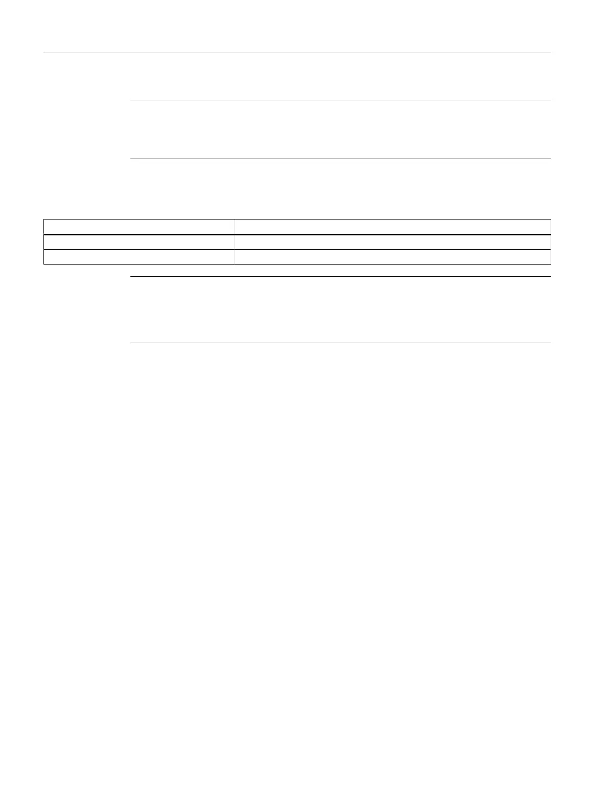
NC/PLC interface signals
Signal Meaning
DB10.DBX58.0 - 7 Collision avoidance: Deactivate protection area group
DB10.DBX234.0 - DBX241.7 Collision avoidance: Activate protection area
Note
The $NP_BIT_NO protection area can be assigned to an arbitrary bit number of the
DB10.DBX234.0 - DBX241.7 interface signals.
The following setting is a prerequisite: $NP_INIT_STAT == "P" (preactivated or PLC controlled)
A detailed description of the machine data is provided in the following documentation:
References
Machine Data and Parameters List Manual
14.4 Graphic machine model editor
This is how you create the machine model from the user interface in a graphic editor that has
2 areas:
● Tree view
In the "Tree" window, model the machine model based on the kinematic chain and allocated
protection areas.
● Graphic view
You also have the option of activating a graphic view.
In the "Graphic" window, you can view and check the result of the machine modeling in the
various views, and, for example, simultaneously correct in the tree view.
Elements that are selected in the tree are highlighted in color in the graphic view.
Collision avoidance
14.4 Graphic machine model editor
SINUMERIK Operate (IM9)
292 Commissioning Manual, 12/2017, 6FC5397-1DP40-6BA1
 Loading...


