Cylinder and parallel cylinder protection area element (Page 312)
Protection area element cone and parallel cone (Page 314)
14.7.3.2 Frame and parallel frame protection area element
You define a coordinate system transformation that will take effect for the following protection
area elements in the "Frame" window.
With elements of this type, you define, for example, additional work offsets or rotations between
protection area elements.
Note
A work offset or coordinate rotation affects all the following protection area elements.
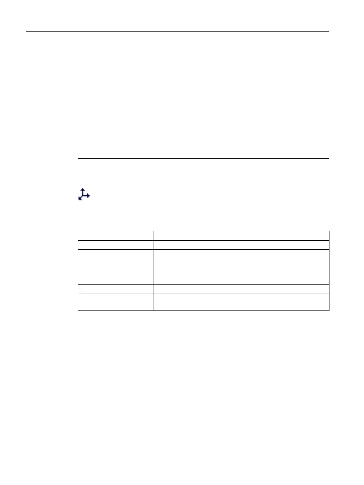
Display in the tree topology
Coordinate system transformations are identified by this symbol in the tree top‐
ology.
Element values
Parameter Meaning
Name Designation that is displayed in the tree structure.
Offset (X) X component of the direction vector.
Offset (Y) Y component of the direction vector.
Offset (Z) Z component of the direction vector.
Rotary axis (X) X component of the rotation vector.
Rotary axis (Y) Y component of the rotation vector.
Rotary axis (Z) Z component of the rotation vector.
Angle of rotation The value by which the system rotates around the rotation vector.
See also
Creating protection area elements (Page 306)
Collision avoidance
14.7 Creating a kinematic structure
SINUMERIK Operate (IM9)
308 Commissioning Manual, 12/2017, 6FC5397-1DP40-6BA1
 Loading...


