Attributes Meaning
Bit mask In the case of an integer variable, a bit mask can be specified in this field. For
a bit mask, the particular signal value is AND'ed before being displayed. After
the mask has been applied, all of the selected bits are moved to the right so
that it looks as if the bit or the bits all start with bit zero.
This means, if all bits with the exception of bit 7 have been masked, then the
integer number that would have been obtained would either have a value of 0
or 1, however, not 0 or 128.
If all of the bits with the exception of bit 7 and 0 have been masked, the resulting
integer number would either have the value 0, 1, 2 or 3, however, not 0, 1, 128
or 129.
Decimal places This setting is used to define how many places to the right of the decimal point
are displayed at the axis identifiers.
Coord. axis The coordinate axes are displayed to the left or right in the graphic window or
there is no display.
Display Y Value input or 0
Scale factor Defines the scale.
Units Displays the measurement unit, e.g. mm/min. The system specifies this and it
cannot be changed.
18.12.3.3 Displaying details of a variable
The most important information and settings are displayed at a glance in the detail window:
● Variable address
● Comment with a description of the variables
● Events
● Channel, axis, access level, mode group, etc.
● Smaller graphic display with the event; when this event occurs the characteristic graphs
are recorded as well as their attributes, such as color or line type.
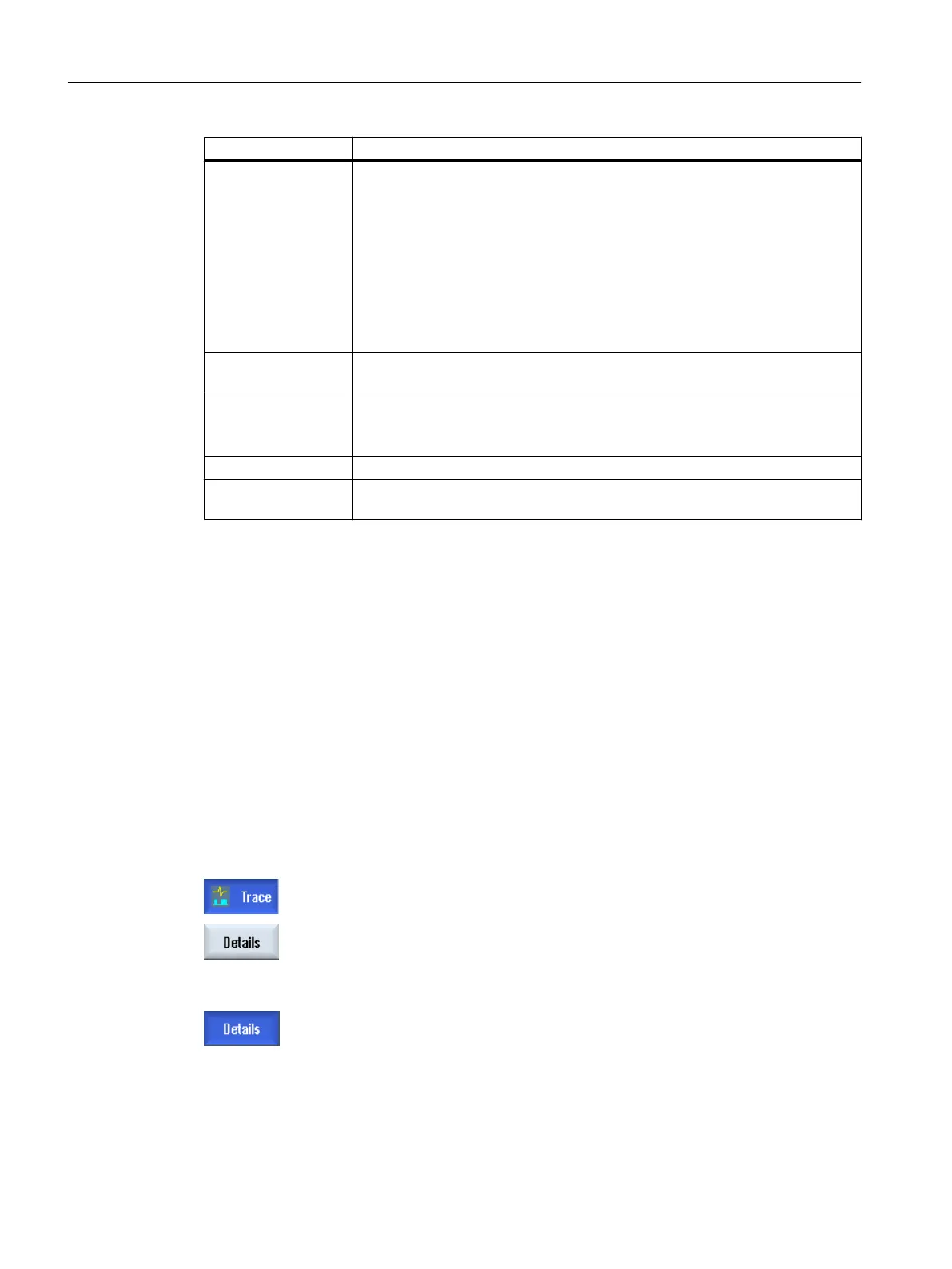
Procedure
1. You are in the "Select variables for trace: ..." window.
2. Position the cursor to the required variable, and press the "Details" soft‐
key.
A subscreen with the most important information as well as the graphic
display is shown in the lower half of the window.
3. Press the "Details" softkey again to display the subscreen.
Service and diagnostics
18.12 Trace
SINUMERIK Operate (IM9)
466 Commissioning Manual, 12/2017, 6FC5397-1DP40-6BA1
 Loading...


