14.7.3.4 Sphere and parallel sphere protection area elements
You can specify the dimensions and position as well as values for the display and collision
monitoring of a sphere-shaped protection area element in the "Sphere" window.
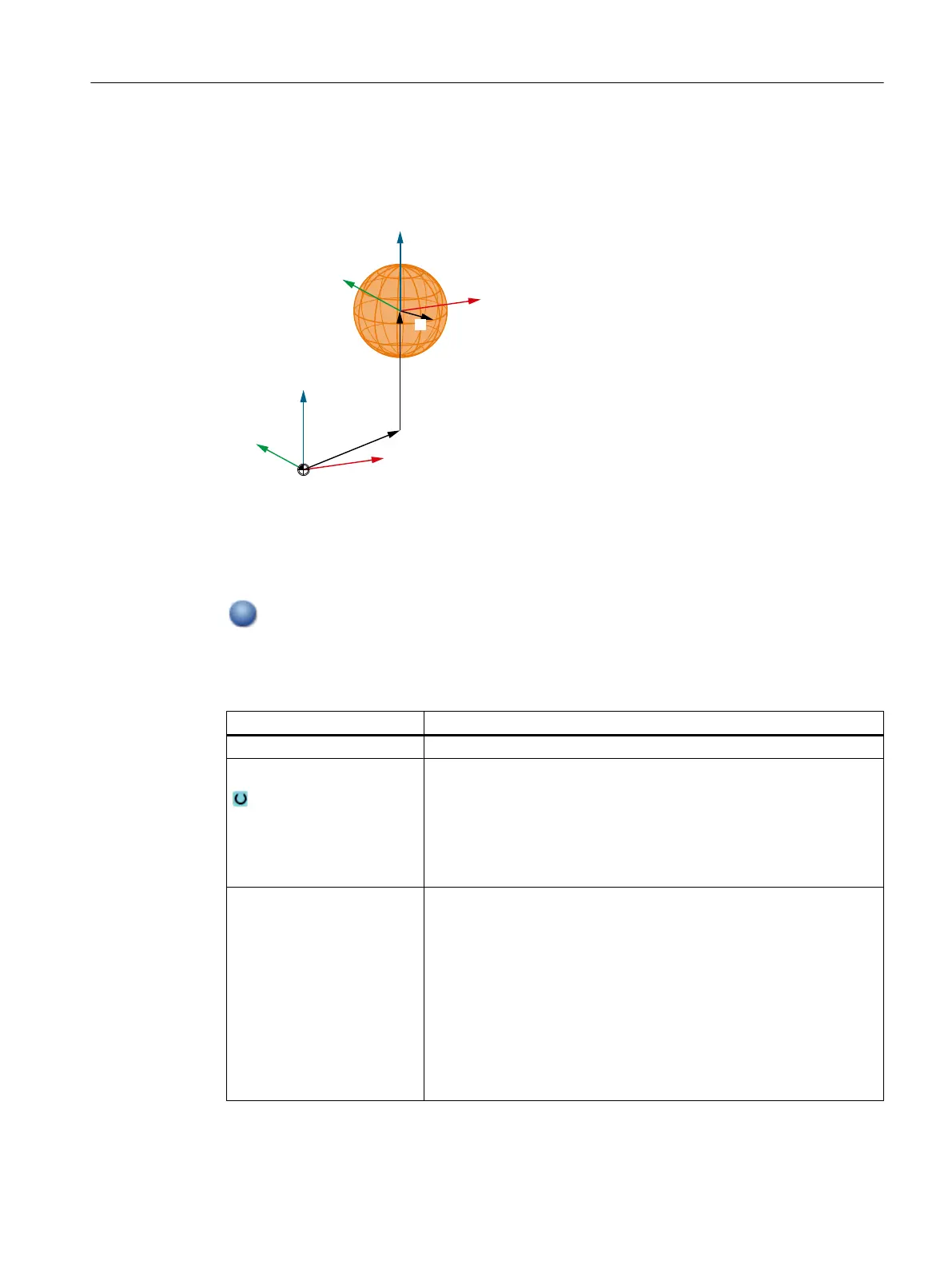
:HOWNRRUGLQDWHQV\VWHP
5
;
<
=
Y
;
<
=
Y
V1 Sum of the offset and rotation between this element and the root element.
V2 Offsets and rotation from the parameters of this element.
Display in the tree topology
Sphere-shaped protection area elements are identified by this symbol in the tree
topology.
Element values
Parameter Meaning
Name Designation, which is displayed in the tree structure.
Color Selection of the color for the protection area element.
● Activate the checkbox "from protection area", if the color of the
associated tool and/or machine protection area should be applied.
Deactivate the checkbox "from protection area" in order to select
any color.
● Select the required color from the selection list.
Detail level Defines from which detail level the protection area or the protection area
elements are displayed on the user interface.
● Activate the checkbox "from protection area", if the detail level of
the associated tool and/or machine protection area should be
applied.
Deactivate the check box "from protection area", if you wish to define
your own detail level for the element.
● Enter the desired level of detail:
– Lowest detail level: 0
– Highest detail level: 3
Collision avoidance
14.7 Creating a kinematic structure
SINUMERIK Operate (IM9)
Commissioning Manual, 12/2017, 6FC5397-1DP40-6BA1 311
 Loading...


