Display in the tree topology
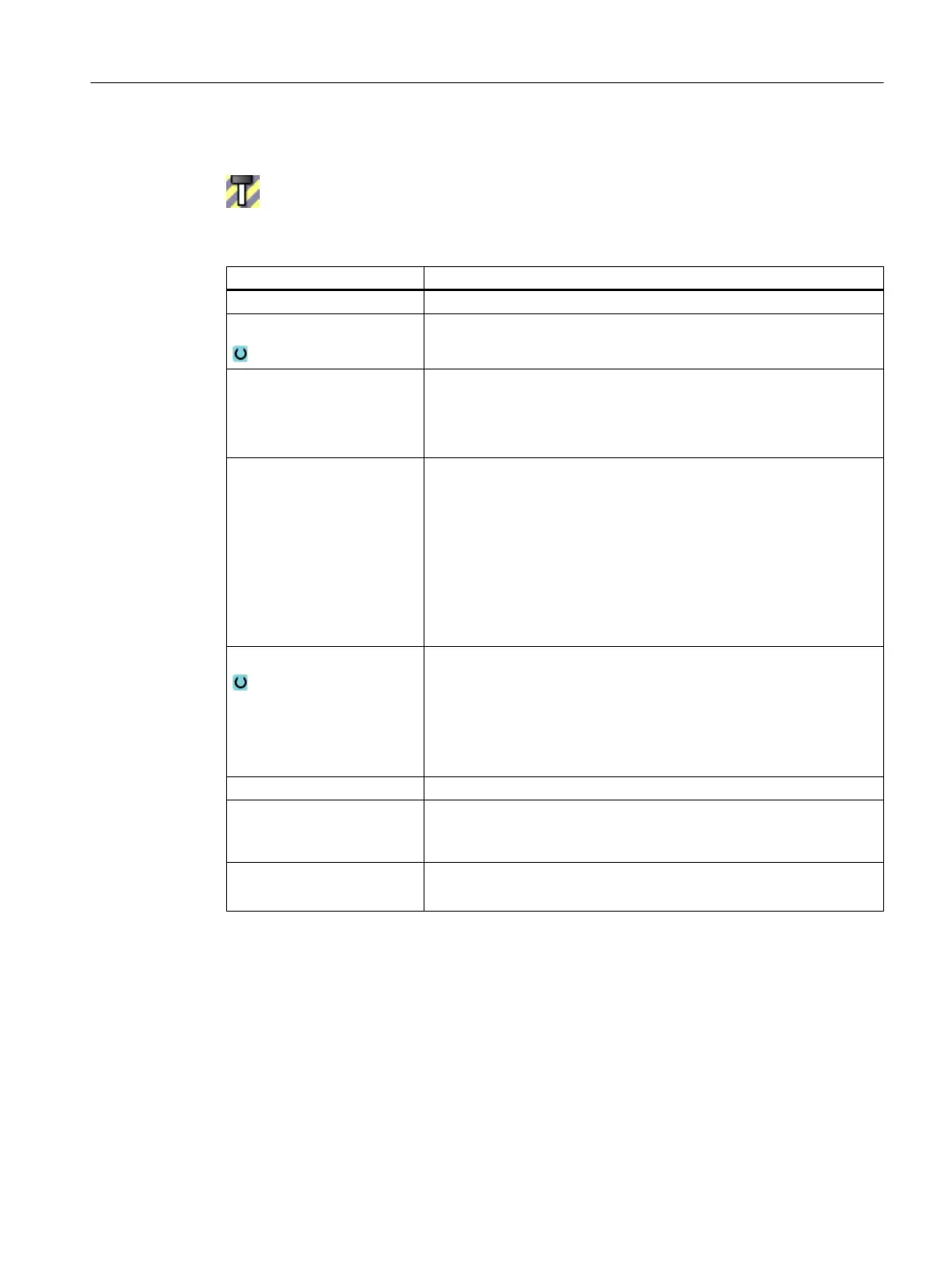
Tool protection areas are identified by this symbol in the tree topology.
Element values
Parameter Meaning
Name Designation that is displayed in the tree structure.
Color Selection of the color
Detail level Defines from which detail level the protection area or the protection area
elements are displayed on the user interface.
● Lowest detail level: 0
● Highest detail level: 3.
PLC bit Only for pre-activation
● - 1
Not activated
● 0 - 63
Activation of the collision avoidance is controlled using the bit
entered here.
The maximum number of PLC bits depends on MD18897. It can be
a maximum of 64.
Activation
● Activates the collision avoidance for the protection area.
● Deactivated
Deactivates the collision avoidance for the protection area.
● Preactivated
Activation of the collision avoidance is controlled using the bit
entered into the "PLC bit".
TO unit Specifies the TO area in which the magazine and tool data are saved.
Magazine When magazine management is active:
Specifies the magazine number in which the tool or magazine location
is located (e.g. for spindle 9998).
Location
● Without magazine management: 1.
● For revolvers: Number of the magazine location
See also
Creating protection areas (Page 303)
14.7.2.3 Machine protection area
In the "Machine protection area" window, you model the machine parts, for example, a table.
You define the parameters to monitor and display the element.
Collision avoidance
14.7 Creating a kinematic structure
SINUMERIK Operate (IM9)
Commissioning Manual, 12/2017, 6FC5397-1DP40-6BA1 305
 Loading...


