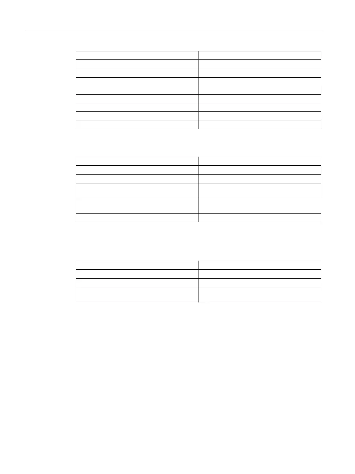
Template Description
feed_traverse_line_hori.fxw Horizontal line to illustrate the tool path during feed
feed_traverse_line_vert.fxw Vertical line to illustrate the tool path during feed
dimensioning_lines_hori.fxw Horizontal projection lines
dimensioning_lines_vert.fxw Vertical projection lines
z1_inc.fxw Horizontal dimension line with the identifier Z1
x1_inc.fxw Vertical dimension line with the identifier X1
3d_coordinate_origin.fxw 3D coordinate origin
3d_zero_point.fxw 3D zero point
Turning
Template Description
turning_blank.fxw The blank for turning technology: A simple cylinder
turning_centerline.fxw Center line
turning_centerpoint.fxw Coordinate origin to display the zero point in the
WCS
turning_refpoint.fxw Reference point, for example, for a machining op‐
eration
turning_machining_area.fxw Boundary lines for the machining area
Milling
Template Description
milling_blank.fxw The blank for milling technology: A simple cube
milling_centerline.fxw Center line
milling_refpoint.fxw Reference point, for example, for a machining op‐
eration
C.3 XML commands
C.3.1
Overview
The scene description file (extension .xml) is required so that the X3D Viewer can access the
graphics. In the scene description file, you assign the scene names that are called from the
configuration to the times in the .x3d file (time sensor) at which the graphics are positioned.
Animated elements
C.3 XML commands
SINUMERIK Integrate Run MyScreens
218 Programming Manual, 10/2015, 6FC5397-3DP40-5BA3

 Loading...


