8.2 Analog spindle
Machine axis index for analog spindle
For a spindle which is not assigned to any drive (FD, MSD, SLM), the power display can be
controlled via the PLC.
In order that the operating software identifies the spindle as analog spindle, enter the axis
index of the analog spindle in the following machine data:
MD51068 $MNS_SPIND_DRIVELOAD_FROM_PLC1 Machine axis index spindle 1
Utilization display from the PLC
Machine axis index of a spindle (analog) that draws the data for the utilization display in
the T,F,S window from the PLC (DB1900.DBB5006).
8.3 Leadscrew error compensation
Instead of transferring the compensation data via the part program or INI file to the NC, you
can enter and check
the compensation data for all axes or change the configuration in an input
screen.
Finally, the changed data is activated in the NC in one step. The machine data required when
activating is set automatically.
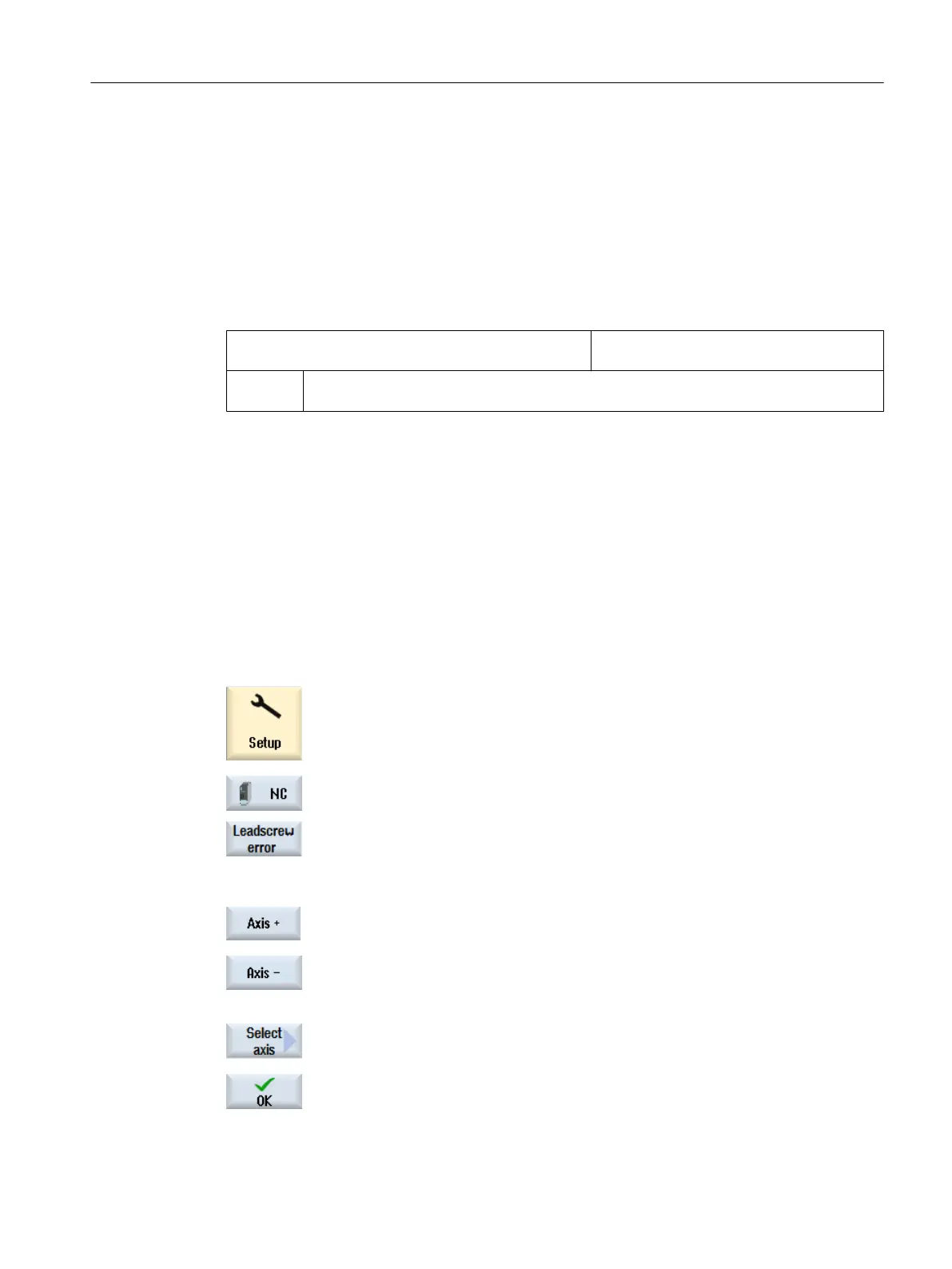
Procedure
1. Select the "Start-up" operating area and press the "NC" softkey.
2. Press the "Leadscrew error" softkey.
The "Values of the Compensation Tables" window opens and displays
the default compensation tables
for an axis or, if no compensation values
are available, the measuring system used.
3. Press the "Axis +" or "Axis -" softkey to select the desired axis.
- OR -
Press the "Select axis" softkey.
The "Axis Direct Selection" window opens. Position the cursor on the de‐
sired axis and confirm with "OK".
Spindle function
8.3 Leadscrew error compensation
SINUMERIK Operate
Commissioning Manual, 10/2015, 6FC5397-3DP40-5BA3 207

 Loading...


