5.5.3 Example: Circuitry for a CU with line contactor
Example
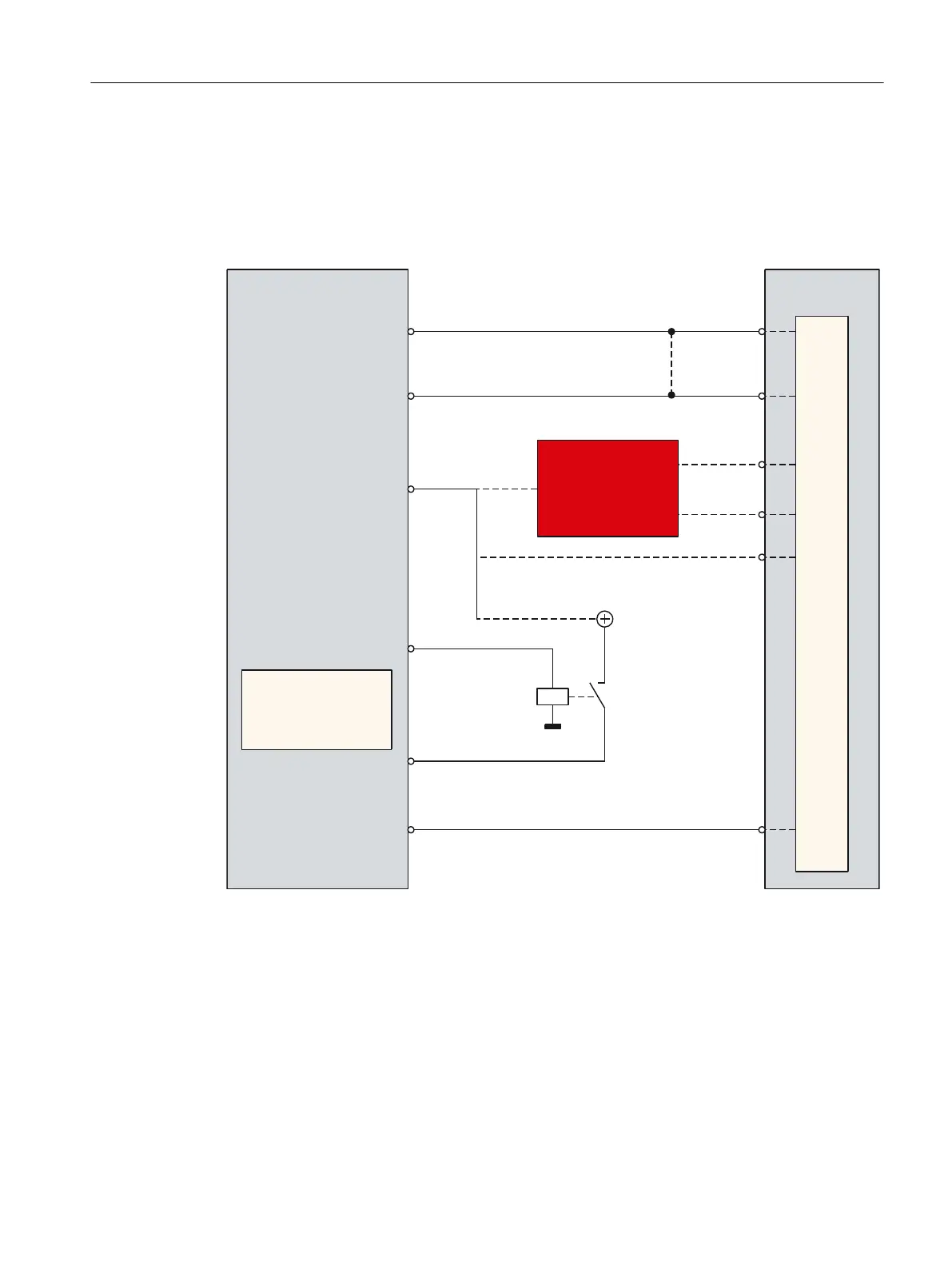
The circuitry shown refers to the assignment of the terminals in the previous chapters.
;
;
;
;
;
;
9
U
U
2))
2))
U
3/&&
8
2XWSXW
,QSXW
,QSXW
2XWSXW
2XWSXW
,QSXW
/LQHFRQWDFWRU
R
U
RU
,QSXW
2XWSXW
,QSXW
2XWSXW
2XWSXW
,QSXW
-XPSHU!!
:LWKRXW3/&ORJLF
,QIHHGRSHUDWLRQ
/LQHFRQWDFWRUIHHGEDFN
VLJQDO
/LQHFRQWDFWRUFRQWURO
1RWH
%,&2LQWHUFRQQHFWLRQRI
OLQHFRQWDFWRUFRQWURO
DFFWRWHUPLQDOGLDJUDP
UHTXLUHG
,QIHHGUHDG\WRVWDUW
6DIHW\UHOD\
(0(5*(1&<
(QDEOHVYLDWKH3/&XVHUSURJUDP
Figure 5-20 Circuitry for a Control Unit with line contactor
Smart Line Module connection
The connections for the digital in/outputs X122 and X132 are on the rear side of the control.
Commissioning the drive
5.5 Terminal assignments
CNC commissioning
Commissioning Manual, 10/2015, 6FC5397-3DP40-5BA3 149

 Loading...


