7.2 Interfaces to the operating software
Overview
To process these service/maintenance tasks, you have the following options:
●
Managing the data in the PLC user program using the programming tool.
●
Creating the maintenance tasks via an XML interface.
Using this segmentation, inconsistencies between the PLC block and the XML scripts are
avoided if the PLC block is changed in the PLC user program via the programming tool or as
a result of a commissioning archive.
Configuration
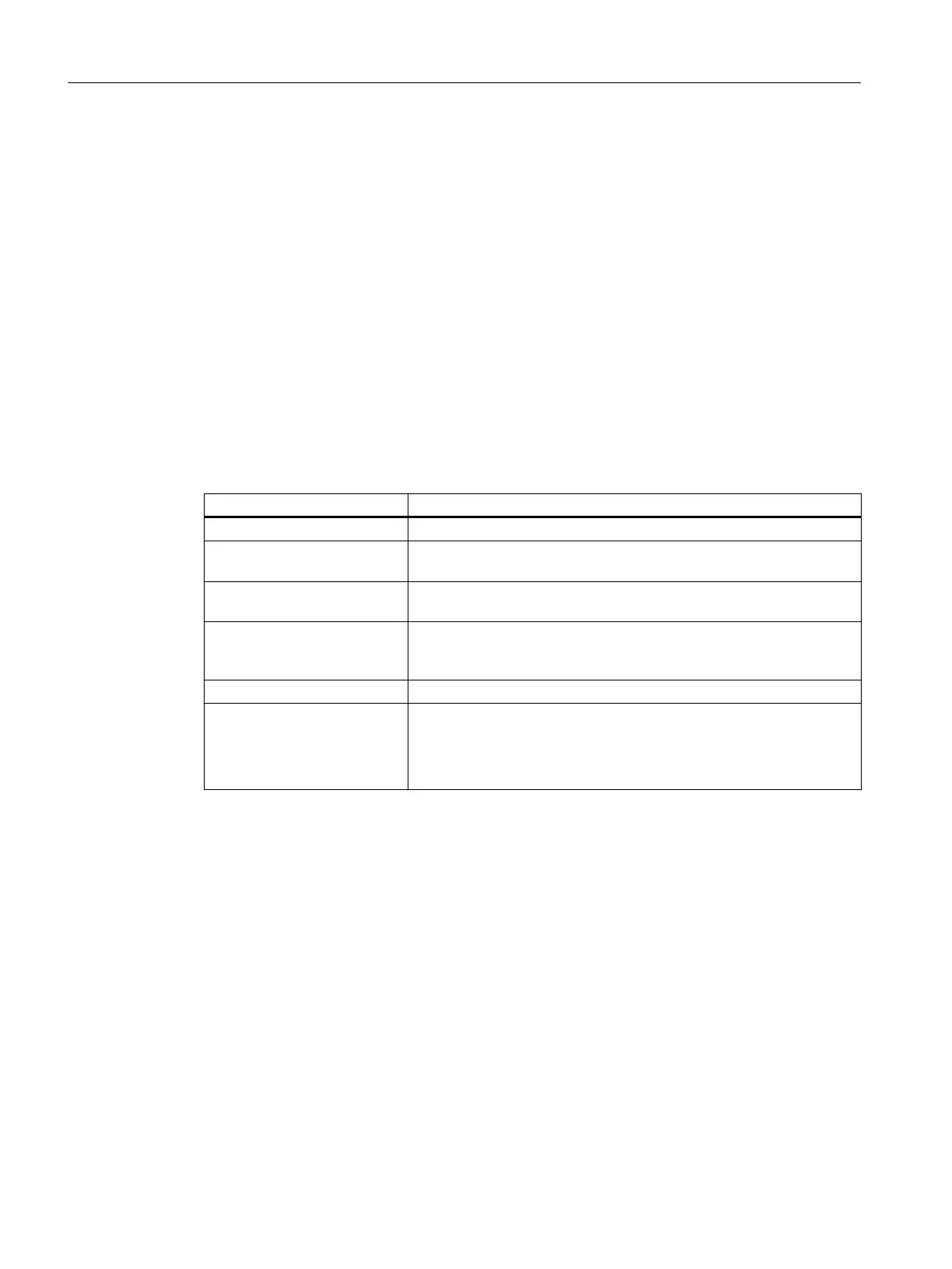
You can configure up to 32 maintenance tasks. The following columns are shown in the
configuring mode:
Designation of the column
Meaning
Maintenance task Name of the maintenance task
Interval [h] Maximum time until the next maintenance in hours; if this value ≠ 0,
this data set is accepted by the PLC as a valid maintenance task.
1st warning [h] Time
in hours after which the first warning is displayed; this value must
be less than that of the interval.
Number of warnings Number of warnings that are output by the PLC before the PLC sets
the
alarm bit for
the last time after the interval has expired (remaining
time == 0).
Remaining time [h] Time until the interval expires in hours.
Status
● A green check mark indicates that the time up to the next
maintenance is still running.
●
A red clock symbol indicates that there is a maintenance task to
be performed.
The dialog is called with different contents depending on the access level.
Configuration mode
Access level 2: Service
Maintenance tasks can be
created, changed and also deleted in this mode. The maintenance
tasks can also be acknowledged. All columns are visible. Navigation between the columns is
with <Tab> or <Key Left/Right>.
Service Planner
7.2 Interfaces to the operating software
CNC commissioning
230 Commissioning Manual, 10/2015, 6FC5397-3DP40-5BA3

 Loading...


