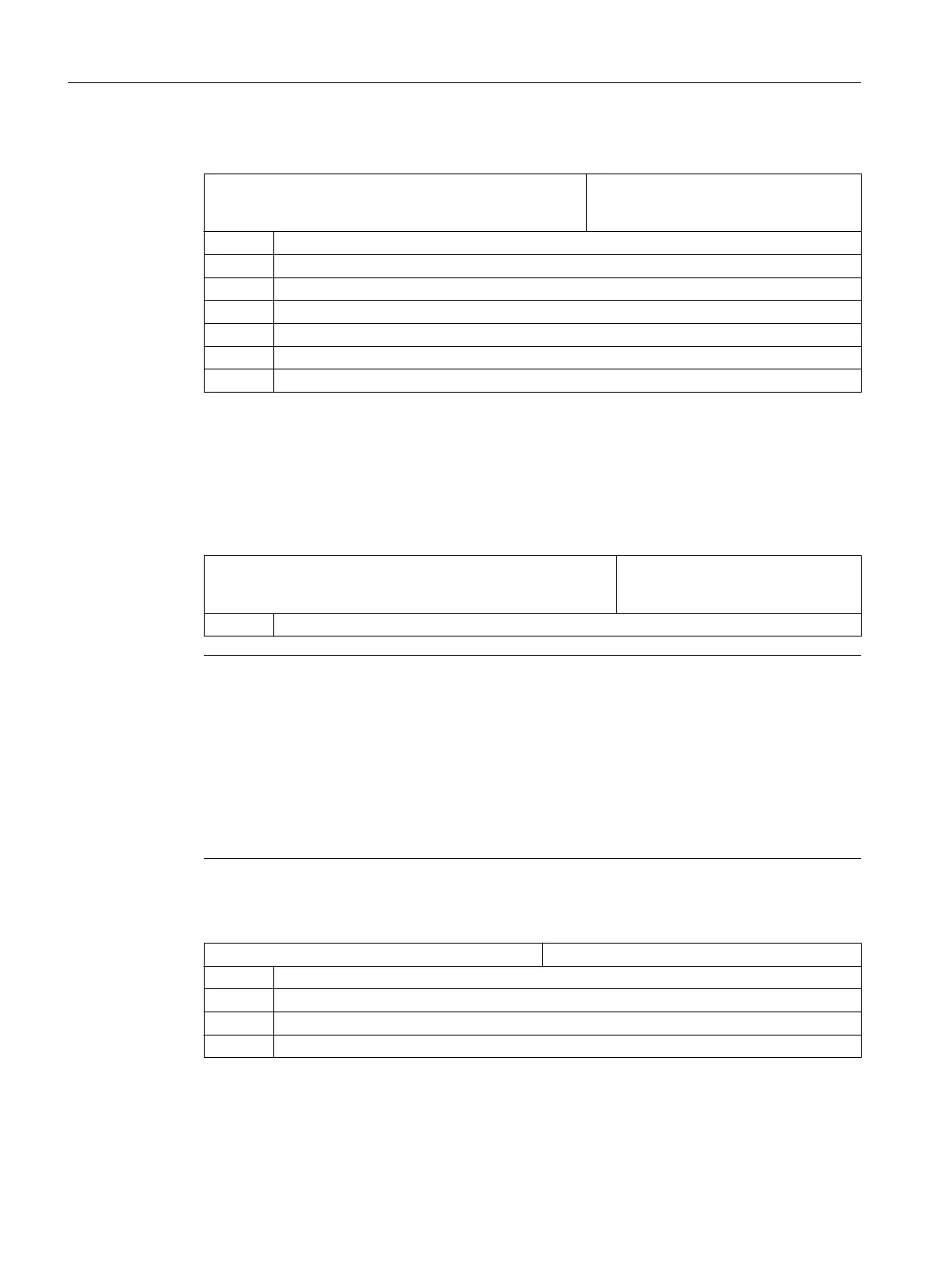
General cycle setting data
SD54780 $SNS_J_MEA_FUNCTION_MASK_PIECE Configuration of the input screens for
measuring in the "Machine" operating
area in the JOG operating mode.
= 512 Default value
Bit 2 = 1 Activates measurements with an electronic probe.
Bit 3 = 1 Selects the probe calibration data, enable.
Bit 6 = 1 Selects ZO offset in the basis reference (SETFRAME), enable.
Bit 7 = 1 Selects ZO offset in the channel-specific basic frame, enable.
Bit 8 = 1 Selects ZO offset in the global basic frame, enable.
Bit 9 = 1 Selects ZO offset in adjustable frames, enable.
7.9.3.2 Measuring tools at the milling machines
Measuring feedrate for tool measurement in JOG and AUTOMATIC
SD55628 $SCS_MEA_TP_FEED_MEASURE Calibrate measuring feedrate for tool
probe and measure tool with station‐
ary spindle.
= 300 Default value
Note
Measuring feedrate for tool measuring
All
measuring
cycles
use
the value saved in SD54636 or SD54651 as the measuring feedrate
after the tool probe has been calibrated. A different measuring feedrate can be assigned for
each calibration field [n].
When calibrating the probe, either the measuring feedrate from
SD55628 SCS_MEA_TP_FEED_MEASURE is used, or the measuring feedrate can be
overwritten in the input screen when calibrating. To do this,
SD54762 $SNS_MEA_FUNCTION_MASK_TOOL bit 4 must be set to 1.
In the following setting data, index [k] stands for the number of the current data field (probe
number -1) of the probe.
SD54633 $SNS_MEA_TP_TYPE[k] Probe type, cube/disk
= 0 Cube (default value)
= 101 Disk in XY, working plane G17
= 201 Disk in ZX, working plane G18
= 301 Disk in YZ, working plane G19
Configuring cycles
7.9 Measuring cycles and measurement functions
SINUMERIK Operate
180 Commissioning Manual, 10/2015, 6FC5397-3DP40-5BA3

 Loading...


