Procedure
1. The "S1 Spindle Diagnostics" window is open.
The "S1 Clamping System" window is open without the "S-Monitor" software option.
2. Press the "Clamping system" softkey.
The "S1 Clamping System" window opens and displays the acquired data.
3. Press
the "Statistics" softkey to read out the clamping times and perform a diagnosis of the
clamping system.
The "S1 Clamping System Statistics" window opens and displays the acquired data.
- OR -
Press the "Back" softkey to return to the data overview.
8.4.8 Clamping system: Speed limits
For safety reasons and to protect the spindle, only maximum speeds are permitted for certain
clamping states. The drive limits the spindle speed in the respective clamping state to the
entered speed.
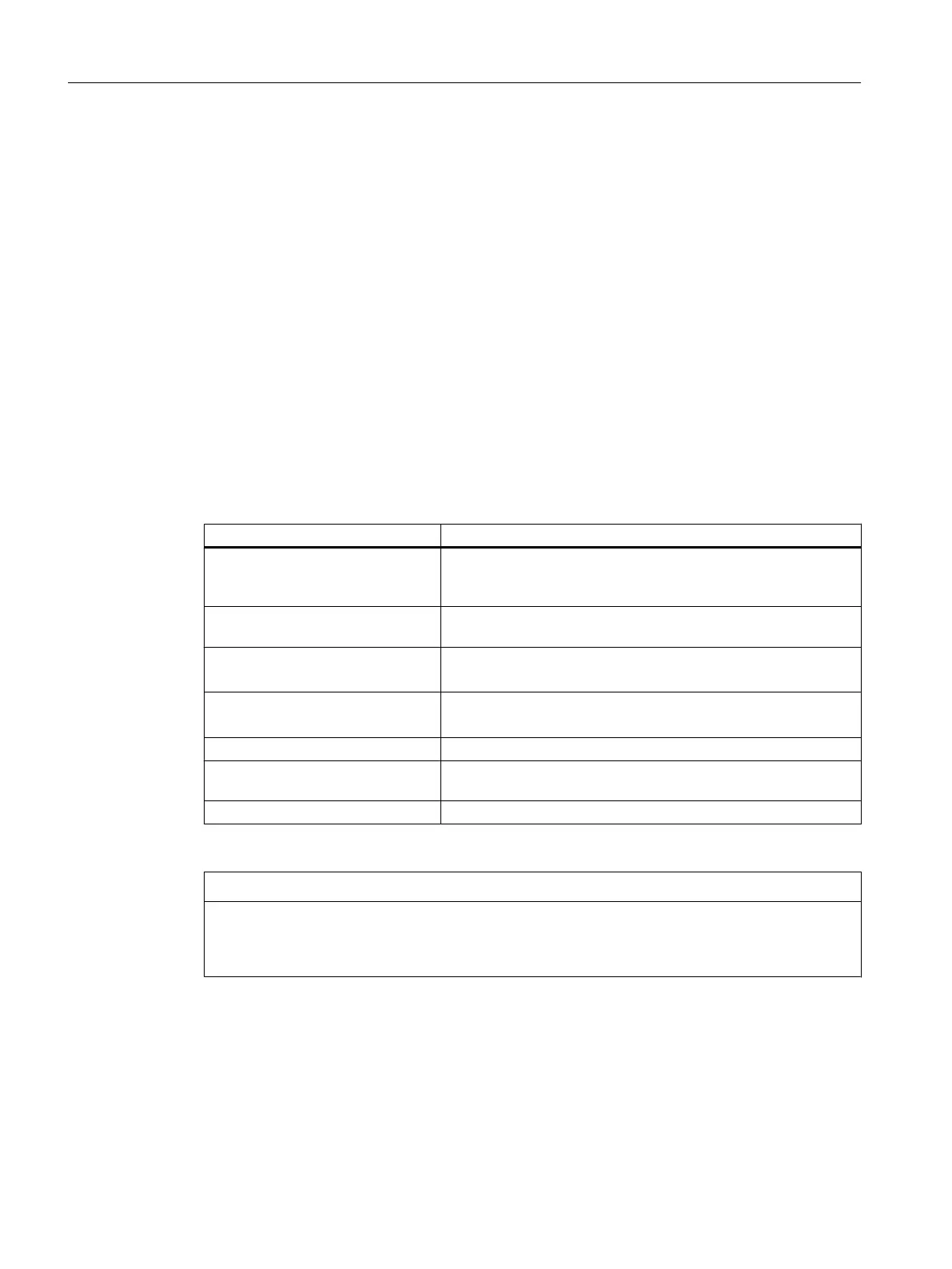
Clamping state Meaning
Released The tool clamping system is in contact with the release plunger.
Please note: The release
plunger presses with the release force
on the clamping system.
Clamping The tool clamping system is in the transition state from "Re‐
leased" to "Clamped with tool".
Releasing from state
"Clamped with tool"
The tool clamping system is in the transition state from "Clamped
with tool" to "Released".
Releasing from state
"Clamped without tool"
The tool clamping system is in the transition state from "Clamped
without tool" to "Released".
Clamped with tool The tool clamping system is in the "Clamped with tool" state.
Clamping without tool The tool clamping system is in the transition state from "Clamped
with tool" to "Clamped without tool".
Clamped without tool The tool clamping system is in the "Clamped without tool" state.
You can adapt the preset speed limits to your requirements by pressing the "Change" softkey.
NOTICE
Damage to the spindle through too high a speed
Changes to the preset speed limits can result in safety-relevant changes of the operating
states and to damage on the spindle.
Spindle function
8.4 Spindle diagnostics
SINUMERIK Operate
216 Commissioning Manual, 10/2015, 6FC5397-3DP40-5BA3

 Loading...


