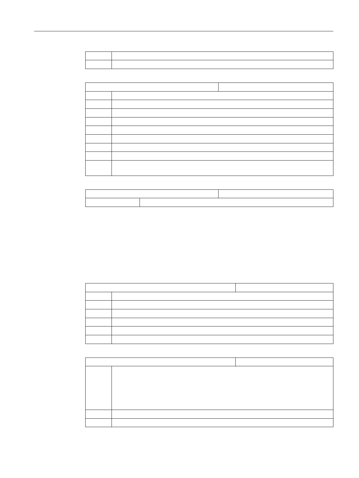
= 18 G18 plane (permanently set)
= 19 G19 plane
MD52212 $MCS_FUNCTION_MASK_TECH Cross-technology function screen
Bit 0 Enable swivel with tool holder
= 0 Swivel plane, swivel tool not enabled
= 1 Swivel plane, swivel tool enabled
Bit 1 Optimized travel along software limit switches
= 0 No optimized travel along software limit switches
= 1 Optimized travel along software limit switches
Bit 5 Call block search function SERUPRO.
= 0 CYCLE207 is not called in the block search cycle PROG_EVENT.SPF.
= 1 The cycle for SERUPRO (CYCLE207) is called in the block search cycle
PROG_EVENT.SPF
MD52240 $MCS_NAME_TOOL_CHANGE_PROG Tool change program for G code steps
= Program name The associated program is called for tool change.
7.2 Technology cycles for drilling
Drilling technology
You
can
set
drilling
technology using the following channel-specific configuration machine data
and channel-specific cycle setting data.
MD52216 $MCS_FUNCTION_MASK_DRILL Drilling function screen form
Bit 0 Tapping cycle CYCLE84, technology input fields
= 0 Hide input fields
= 1 Display input fields
Bit 1 Tapping cycle CYCLE840, technology input fields
= 0 Hide input fields
= 1 Display input fields
SD55216 $SCS_FUNCTION_MASK_DRILL_SET Drilling function screen form
Bit 1 Boring CYCLE86: Take into account the rotation of the tool plane when positioning the
spindle
Note:
Spindle
direction of rotation
M3/ M4 and direction of rotation of the rotary axes must be set
according to DIN. For SPOS=0, the tool cutting edge points in the + direction of the 1st axis
of the plane (for G17, to X+).
= 0 Do not take into account the rotation of the tool plane when positioning the spindle (SPOS).
= 1 Take into account the rotation of the tool plane when positioning the spindle (SPOS).
Configuring cycles
7.2 Technology cycles for drilling
SINUMERIK Operate
Commissioning Manual, 10/2015, 6FC5397-3DP40-5BA3 79

 Loading...


