Design Guidelines
Transport System Design
102 MagneMotion
Rockwell Automation Publication MMI-UM002F-EN-P - October 2022
Various materials can be used to construct the vehicles in a MagneMover LITE transport sys-
tem. Any material that is used must be able to carry the payload without deflecting while sup-
porting the magnet array in the correct relationship to the motors. In general, use a lighter
weight vehicle to maximize the acceleration capability of the system for moving the payload.
Wheels or rollers are used to support the vehicles on the guideway while allowing the vehicles
to move freely upstream and downstream. They also maintain a consistent space between the
magnet array that is attached to the vehicle and the MM LITE motors (vehicle gap). Wheel
and roller materials affect the frictional resistance, which affects the amount of thrust that is
required to move a vehicle. The selected material must be hard enough to provide a low roll-
ing resistance but, depending on the environment the system is used in, soft enough to mini-
mize excess noise when traversing the joints between guideway sections.
Vehicles can have one or two magnet arrays that are attached to the surface closest to the
motors based on the use of the vehicle (see Figure 3-29). In MagneMover LITE systems,
using two arrays is typically when vehicles carry a payload that is larger than the recom-
mended payload for a vehicle with one magnet array.
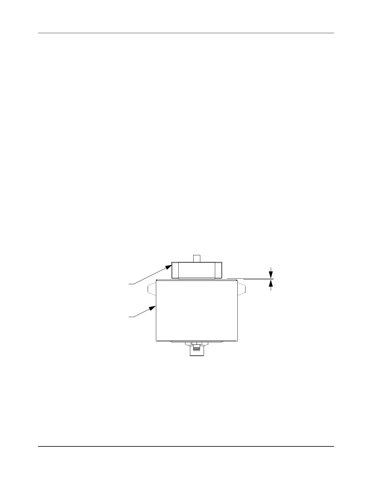
Vehicle Gap
The vehicle gap, which is shown in Figure 3-25, is the distance that is maintained between the
magnet array and the MM LITE motor. This gap must be maintained throughout the transport
system to make sure that the vehicle operates consistently. The larger the gap the lower the
thrust. The smaller the gap the greater the risk of contact between the magnet array and the top
of the motor, which could cause damage.
Figure 3-25: Vehicle Gap
Standard MM LITE motors have integral rails that make sure that a consistent vehicle gap is
maintained throughout the MagneMover LITE transport system. For systems using G3 pucks,
this is 1 mm ±0.5 mm and for G4.2 and later pucks, this is 1.5 mm ±0.5 mm. When designing
a guideway to be used with the MagneMover LITE railless motors, the same gap and toler-
ance must be maintained to meet the standard thrust requirements.
The guide rails on which the vehicles move are typically held flat to within ±0.5 mm, with a
vehicle gap of 1…2 mm more than the tolerance of the track and vehicle. The greater the tol-
Magnet Array
MM LITE Motor
Vehicle Gap
 Loading...


