Design Guidelines
Transport System Layout
MagneMover LITE User Manual 77
Rockwell Automation Publication MMI-UM002F-EN-P - October 2022
Nodes
Once all paths have been identified on the MagneMover LITE transport system layout, the
nodes that connect those paths must be defined (see Figure 3-3 for an example). Node defini-
tion includes identifying the type of node being used.
Nodes define the beginning of all paths and the connections between paths. See the Magne-
Mover LITE Configurator User Manual, MMI-UM008, for a detailed description of nodes
and all node types. The MM LITE transport system supports the following node types:
• Simple Node – Defines the beginning of a path (that is, there is no other path that is
connected at this point).
• Relay Node – Connects the end of a path to the beginning of a path.
• Terminus Node – Defines the start or end of a path where vehicles (pucks) move to or
from the MagneMover LITE transport system.
• Gateway Node – Connects a path in one HLC Control Group in a transport system to
a path in another HLC Control Group within the same transport system.
• Merge Node – Connects the ends of two paths to the beginning of another path.
• Diverge Node – Connects the end of one path to the beginning of two other paths.
• Merge-Diverge Node – Connects the ends of two paths to the beginning of two other
paths.
NOTE: The connections to the motors at the ends of all paths that meet in a node must be
made to the same node controller.
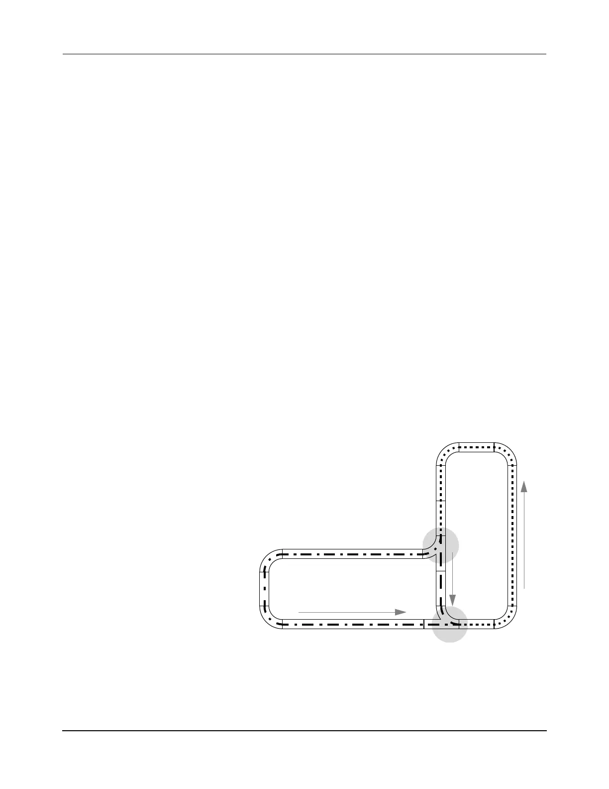
Figure 3-3: Sample MM LITE Transport System Layout Showing Nodes
3 1000 mm motor
6 250 mm motor
5 90° curve motor
2 Right switch
Qty Description
Diverge
3 Paths
2 Nodes
Merge
1 Diverge
1 Merge
NOTE: Arrows indicate direction of forward motion.
Path 3
Path 1
Path 2
 Loading...


