Operation
Controls and Indicators
MagneMover LITE User Manual 331
Rockwell Automation Publication MMI-UM002F-EN-P - October 2022
Synchronization
The Synchronization option for the MagneMover LITE transport system provides the ability
for the end user to more accurately control movement of individual vehicles (pucks) within a
specified zone. More elaborate motion profiles can be implemented, such as jerk control. Syn-
chronization also allows coordinating vehicle motion to that of an external moving element
(for example, robot, filler). Only use the Sync option with those motors that are in a location
where vehicle motion must be synchronized with an external mechanism.
In normal asynchronous operation, the node controllers route the orders from the Host to the
motors and the motors control the profiles (position, velocity, and acceleration) for the vehi-
cles. All asynchronous control is handled through the RS-422 interface from the node control-
ler to the motors.
In synchronous operation the profile (position, velocity, and acceleration) generation for indi-
vidual vehicles is the responsibility of the host controller, which generates profiles for all
vehicles in the synchronization region. This profile requires that the host controller is in
charge of collision avoidance. Once the vehicle leaves the sync region, the MagneMotion con-
trol system picks up profile generation and collision avoidance functions. The vehicle IDs
assigned to the vehicles by the transport system are preserved across non-Sync and Sync
regions.
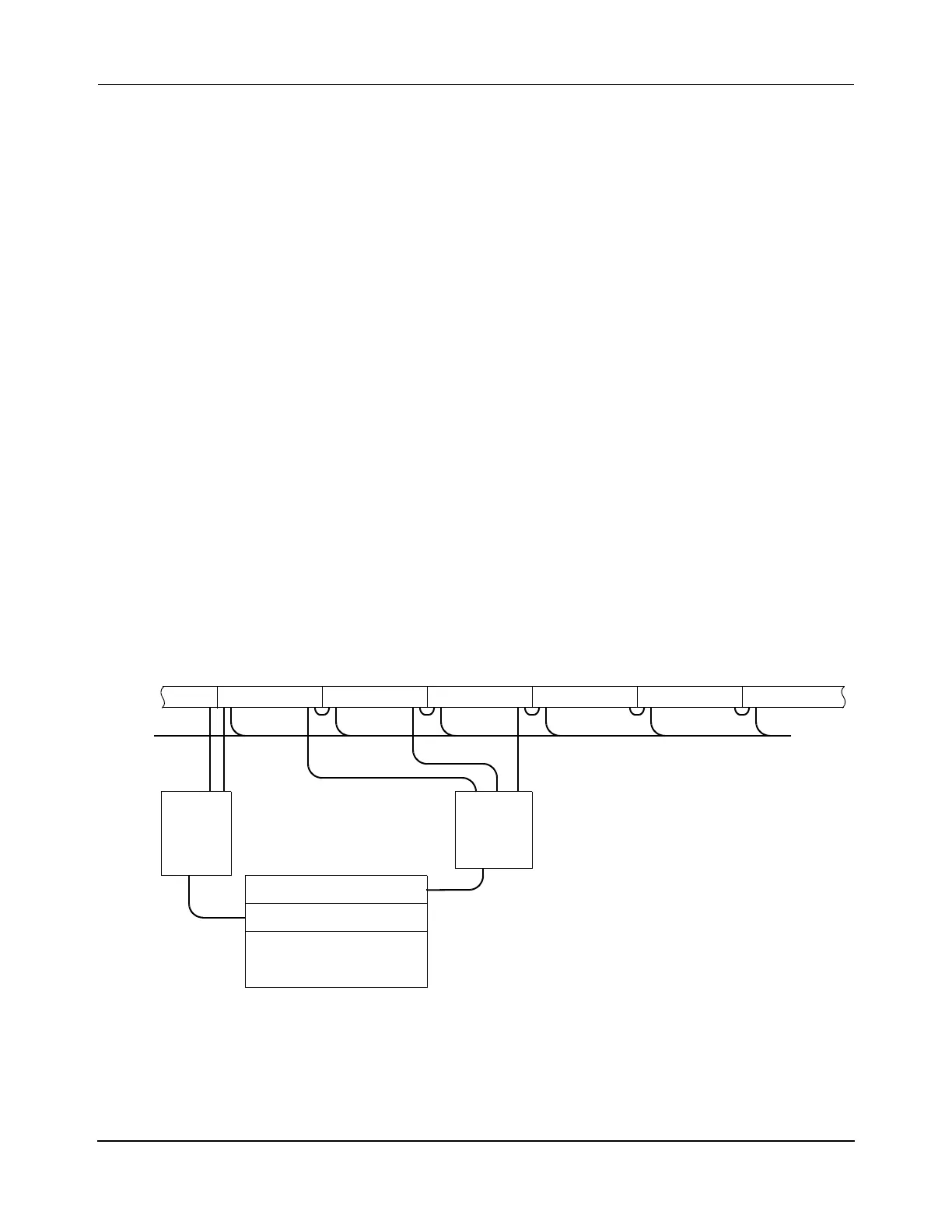
For synchronization, a SYNC IT
™
controller is required for every three motors that are being
synchronized as shown in Figure 6-9. See the LSM Synchronization Option User Manual,
MMI-UM005, for configuration and operation details to use the Sync option with the Magne-
Mover LITE transport system.
Figure 6-9: Transport System Wiring Diagram with Synchronization
NOTE: The SYNC IT controller is powered through its connection to the motors and does
not require any external source of power.
PLC
Sync Motor
SYNC IT
Power
Sync Motor Sync Motor Motor Motor
TCP/IP or EtherNet/IP
EtherNet/IP
NC
Controller
Motor
 Loading...


