Maintenance
Repair
MagneMover LITE User Manual 389
Rockwell Automation Publication MMI-UM002F-EN-P - October 2022
3. Remove all communication cables for the removed motors.
Install New Ethernet Motors
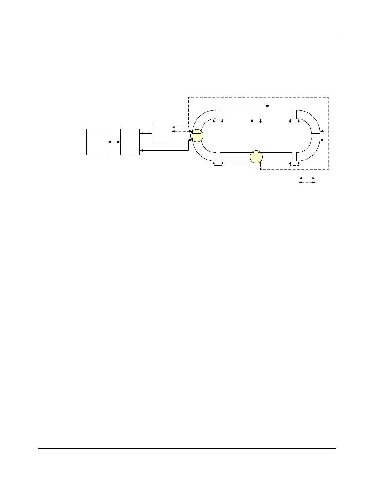
1. Install the Ethernet motors in the transport system as shown in Figure 7-14, see
Replace RS-422 Motors on page 385.
Figure 7-14: Basic RS-422 Loop With Ethernet Motors Added
2. If the system doesn’t have a network switch between the host controller and the HLC,
install a network switch.
A. Reroute the existing connection from the host controller to the node controller
so it runs from the host controller to the network switch.
B. Add an Ethernet connection from the node controller to the network switch.
3. Install the Ethernet cables.
A. Add an Ethernet connection from the network switch to one of the new Ether-
net motors.
B. Add an Ethernet connection from Ethernet motor to Ethernet motor.
4. Reinstall the RS-422 cables.
• Replace the connections to the ends of the RS-422 path.
5. Restore power to the MagneMover LITE transport system where the motors were
replaced.
Create/Revise Configuration Files
1. Revise the Node Controller Configuration File (see the MagneMover LITE Configura-
tor User Manual, MMI-UM008).
A. Make sure that the Ethernet motors are properly defined.
B. Make sure that Relay Nodes are used to connect the new motors to the existing
system as shown in Figure 7-14.
P2M1
x.y.2.1
P2M2
x.y.2.2
HLC &
Node
Controller
Host
Controller
Relay
Node
RS-422 Motor RS-422 Motor
P1M1
P1M2 P1M3
P1M4
P1M5
P1M6
RS-422
Motor
Enet
Motor
RS-422
Motor
RS-422
Motor
Relay
Node
Enet
Switch
Enet Motor RS-422 Motor
Loop Transport System:
Mixed Enet and RS-422 motors, Two Paths
One Enet Chain, One RS-422 Chain
Ethernet
RS-422
Downstream
RS-422
Ethernet
 Loading...


