Design Guidelines
Transport System Design
MagneMover LITE User Manual 119
Rockwell Automation Publication MMI-UM002F-EN-P - October 2022
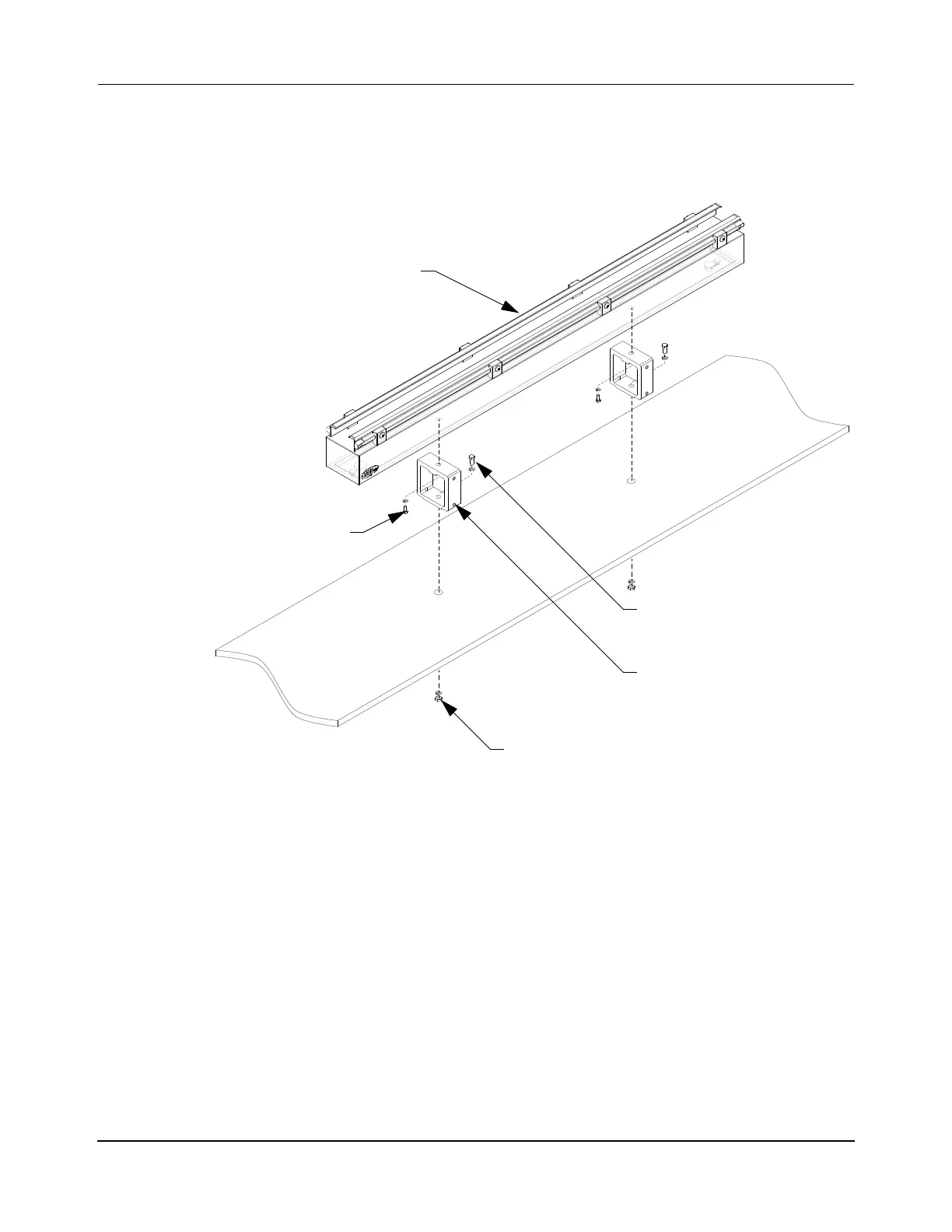
• The standard or adjustable motor mounts can be used to secure the motors to a surface
as shown in Figure 3-46. The motor mounts provide clearance for all cable routing.
This mounting method may not provide for any adjustment of the motor position once
the motor is installed unless adjustment features are provided in the mounting plate.
Figure 3-46: Motor Mounting Using Motor Mount Brackets
When using any of the mounting methods shown.
1. Loosely mount the motors to the motor mounting surface. The motor mounts should
allow the motors a small amount of movement relative to each other.
NOTE: The upstream end of the motor is the end where the power connector is
located (see Figure 4-1 on page 148 through Figure 4-24 on page 171).
2. Make sure that there is consistent spacing between the motors.
3. Make sure that the tops of all motors are coplanar to each other.
4. Treating each motor to motor interface as a separate operation, tighten the motor
mounts. See Align and Secure Motors and Switches for details of the mounting proce-
dure.
Standard Mounting Bracket
M8 Bolt
M6 x 20 mm Bolt
MM LITE 1000 mm Motor
M8 Mounting Hardware
M8 Lock Washer
M6 Lock Washer
 Loading...


