Design Guidelines
Transport System Layout
MagneMover LITE User Manual 75
Rockwell Automation Publication MMI-UM002F-EN-P - October 2022
Motors, Switches, and Vehicles (Pucks)
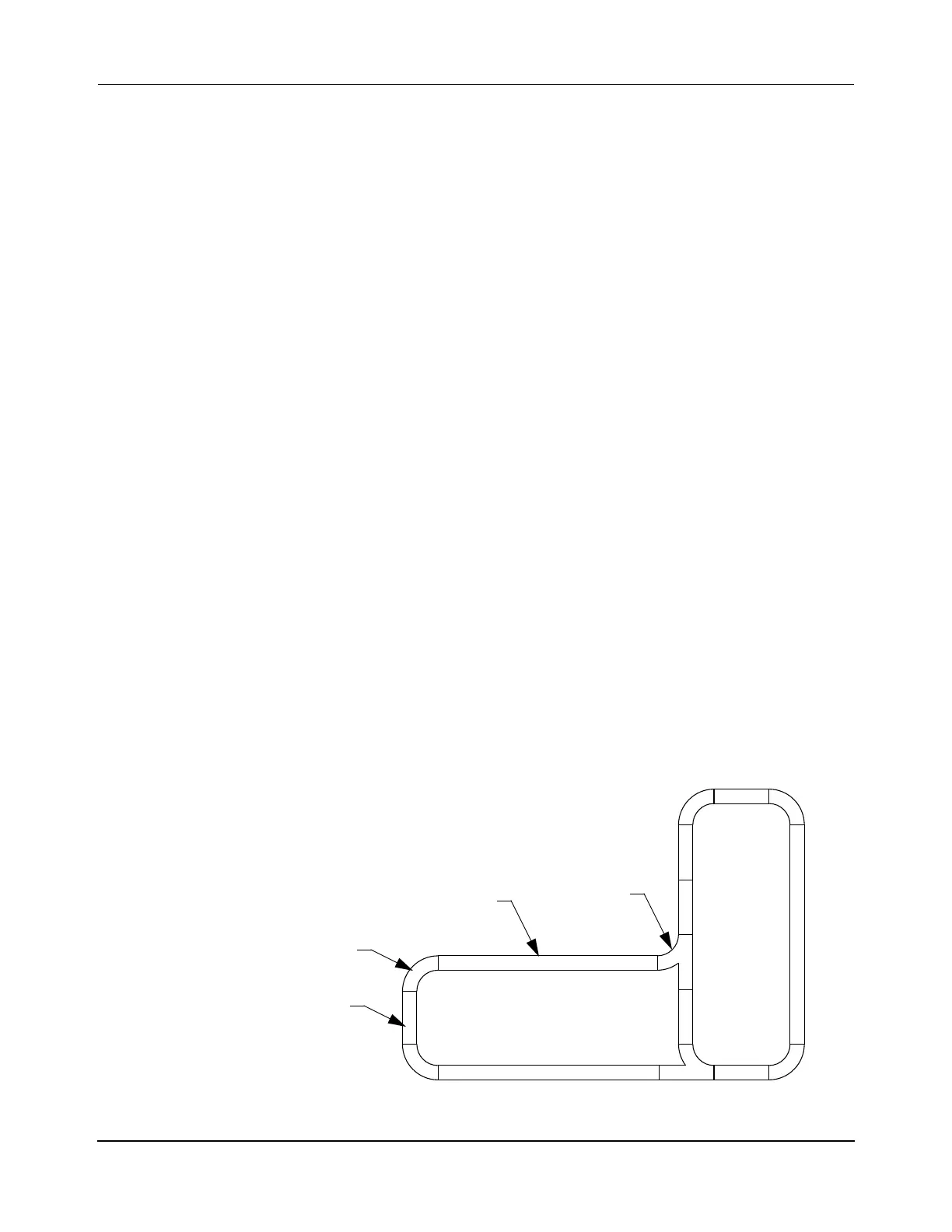
The transport system layout is a plan view layout of the MM LITE transport system. This
drawing identifies each motor and switch (if necessary) in the transport system (see Figure 3-1
for an example). The drawing also includes how they are physically located and any interfaces
to other equipment in the facility.
Motors are used to move the vehicles (pucks) on the transport system. When using multiple
motors, they must be installed so that the end of one motor is physically connected to the end
of the next motor in the same path (see Paths on page 76). The motors can be installed in
either direction, the connections to the motor in the path define the upstream and downstream
ends during commissioning.
Switches connect multiple paths and direct the vehicles (pucks) from one path on the transport
system to another path. All MagneMover LITE switch modules can only be used with pucks
on a standard MM LITE transport system with integral rails.
NOTE: MagneMover LITE switch modules are not available when using the railless motors
for either the precision rail option or for custom designs.
Pucks are the preconfigured independent vehicles with integral magnet arrays that are used on
MagneMover LITE transport systems. Each vehicle (puck) is independently controlled and
provides a platform for securing and carrying the payload in transit. Forward vehicle motion is
from upstream to downstream, however vehicles can move backwards (downstream to
upstream) if necessary. The transport system assigns a unique ID to each vehicle at startup.
This ID is retained until the transport system is restarted, the vehicle is removed through a
Terminus or Gateway Node, or the vehicle is deleted. Additionally, the transport system
makes sure that vehicles do not collide with each other by implementing anti-collision algo-
rithms. It is not necessary to show the vehicles (pucks) on the transport system layout.
NOTE: It can be useful to show facility features on the drawing.
Figure 3-1: Sample MM LITE Transport System Layout Showing Motors
250 mm Motor
1000 mm Motor
90° Curve Motor
Right Switch
3 1000 mm motor
6 250 mm motor
5 90° curve motor
2 Right switch
Qty Description
(typical)
(typical)
(typical)
(typical)
 Loading...


