Specifications and Site Requirements
Electrical Specifications
MagneMover LITE User Manual 219
Rockwell Automation Publication MMI-UM002F-EN-P - October 2022
Table 4-27: MM LITE Power Supply Fuses
Label Description
F1, F2, F3 6.3 x 32 mm, 250V AC (125V DC), 10 A ceramic slow blow fuse
AC PWR 5x20 mm, 250V, 10 A time-lag fuse
Table 4-28: MM LITE Power Supply DC Power Pinouts
Individual Terminals
V+ Propulsion Black
V+ Logic White
V- Return
*
* MagneMotion recommends tying V- Return to RTN.
Red
RTN Green
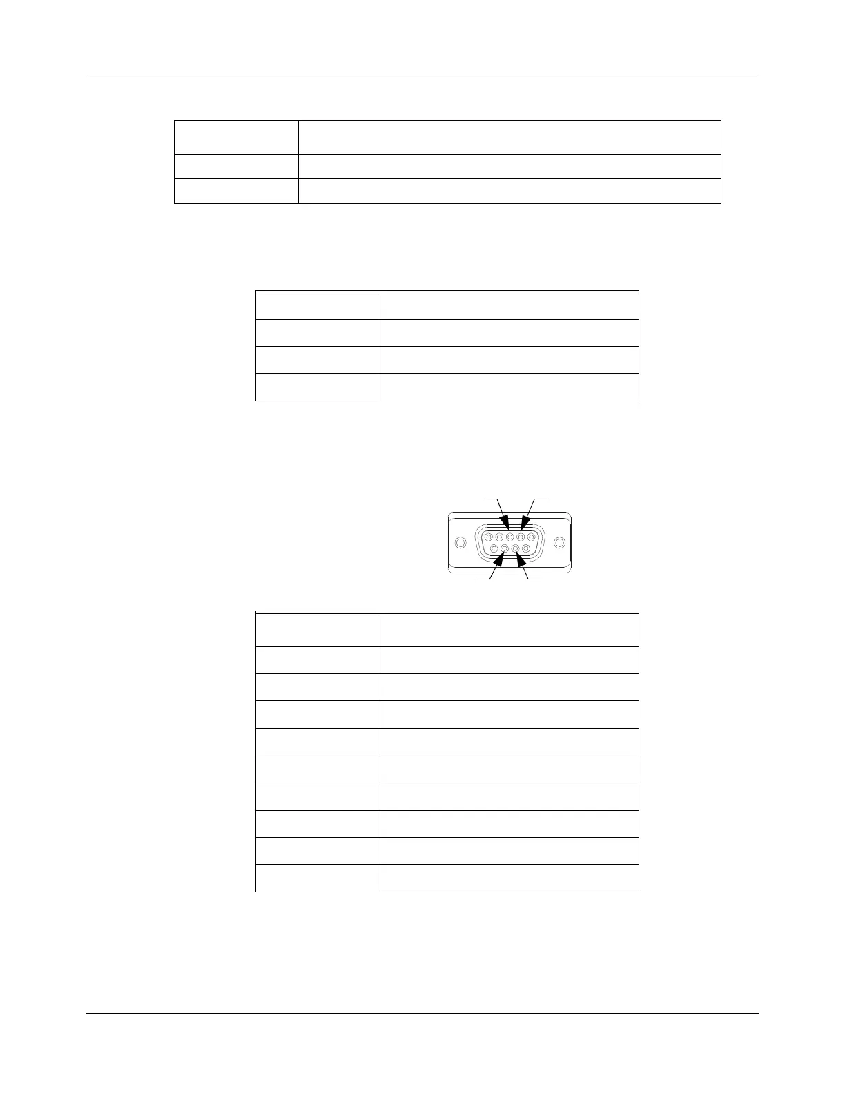
Table 4-29: MM LITE Power Supply DC Enable
DE-9, Socket
Pin Signal
1DC-OK
*
* DC-OK signal is 0…1V when the PS is off and between
3.3…5.6V when the PS is on. The sinking current is 10 mA max-
imum.
2RTN
3 +Bus Enable
†
† Can be shorted via a transistor to enable propulsion power. The
sinking current is 20 mA maximum.
4-Bus Enable
†
5—
6—
7—
8—
9—
 Loading...


