Installation
Transport System Installation
274 MagneMotion
Rockwell Automation Publication MMI-UM002F-EN-P - October 2022
Installing Motor Power Cables
See Figure 4-56 on page 208 through Figure 4-59 for the power connection locations on the
motors and switches and Figure 4-60 for the power connection locations on the MM LITE
power supply. See Figure 5-18 and Figure 5-19 for simplified diagrams of the wiring.
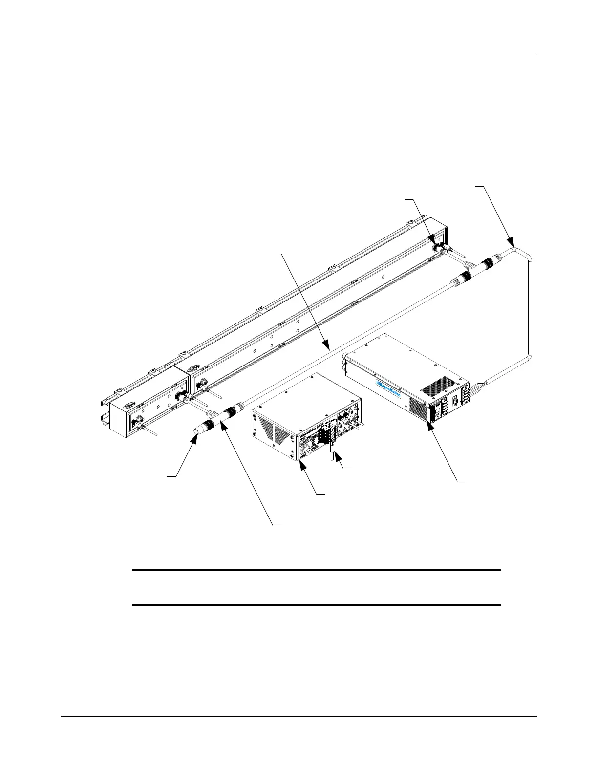
Figure 5-24 shows the power connections being made to the bottom of the motor. The power
connections are the same for motors that use RS-422 communication and for motors that use
Ethernet communication.
Figure 5-24: Power Connections
The AC power connections are made later (see Facilities Connections on page 302). See Elec-
trical Wiring on page 86 to make sure that all power wiring is properly sized. See Table 4-9 on
page 206 when connecting the power cables to the motors to make sure that each chain of
motors does not exceed the rated output of the MM LITE power supply (600 W). MagneMo-
tion recommends that a maximum of 10 motors be connected to J1 or J2 on the power supply
at one time (20 motors per power supply).
NOTICE If a user-supplied power supply is used, it must be
NRTL/ATL approved.
J
1
J
2
G
N
D
J
4
D
C
E
N
A
B
L
E
(
S
E
E
M
A
N
U
A
L
F
O
R
P
I
N
O
U
T
)
3
6
V
D
C
3
0
0
W
3
6
V
D
C
3
0
0
W
G
N
D
V
+
P
R
O
P
U
L
S
I
O
N
V
+
L
O
G
I
C
V
-
R
E
T
U
R
N
V
+
L
O
G
I
C
V
-
R
E
T
U
R
N
V
+
P
R
O
P
U
L
S
I
O
N
J
3
Motor Power Connector
MM LITE
Power Bus Cable
T-Splitter Power Cable
Power Bus
Power Cable
Power Supply
Ground
Node Controller
(NC-12 Shown)
End Cap
 Loading...


