Operation
Theory of Operation
MagneMover LITE User Manual 321
Rockwell Automation Publication MMI-UM002F-EN-P - October 2022
Anti-Collision
The MagneMover LITE transport system allows only one vehicle per motor block. This block
allocation is the basic rule on which the anti-collision feature of the MM LITE transport sys-
tem controls is founded. Since two vehicles are not allowed to be in the same motor block,
they cannot collide. This block allocation affects how many vehicles can fit on a motor or
path.
Also, the magnet arrays on the vehicles have a slight repulsive force that causes them to pas-
sively separate from each other a short distance when they are manually pushed together and
not being servoed (actively controlled). The distance they passively separate varies based on
vehicle (puck) and track conditions (including friction).
The vehicles can be commanded to a tighter spacing but this spacing requires constantly driv-
ing the motor to force them together. They can be commanded to a pitch where they are prac-
tically in contact with each other but if this constant, close position condition is held too long
the motors reach a thermal limit and shut down. This tight spacing can be done on occasion
but it cannot be a standard part of a process.
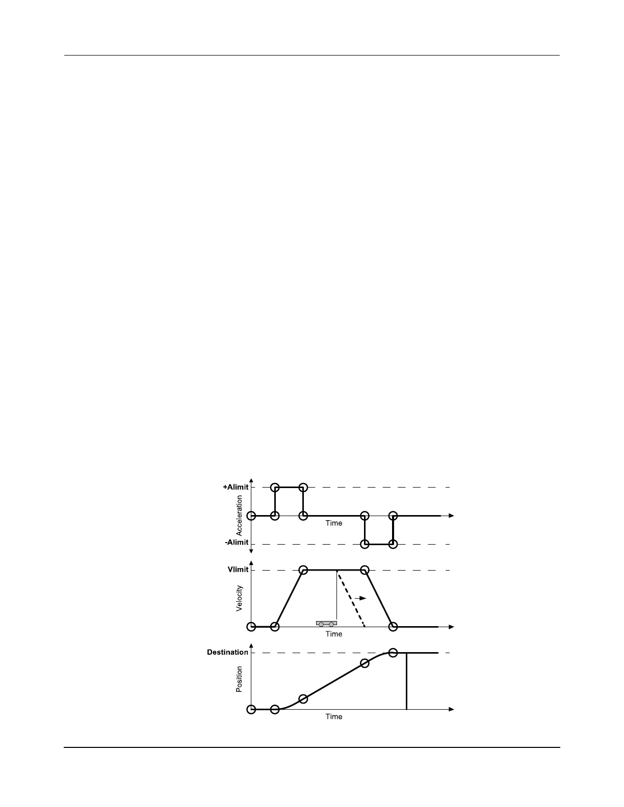
Safe Stopping Distance
Standard vehicle control and operation make sure that vehicles (pucks) always have a safe
stopping distance (brick-wall headway). Figure 6-5 shows acceleration, velocity, and position
versus time for the standard vehicle motion profile. Permission for vehicle motion is granted
as required on a block-by-block basis. This permission keeps vehicles on their move profile
(solid heavy line) and provides a safe stopping distance (dashed heavy line) based on the cur-
rent velocity and commanded acceleration of the vehicle. This stopping distance can be found
by dividing the square of the current velocity of a vehicle by twice its acceleration (V
2
/2a).
Figure 6-5: Vehicle Movement Profile
 Loading...


