Installation
Transport System Installation
MagneMover LITE User Manual 265
Rockwell Automation Publication MMI-UM002F-EN-P - October 2022
1. Insert two M8 T-nuts and rotate into position in the appropriate channels of the frame.
2. Remove the six screws on each end of the bottom with a Phillips bit.
3. Install the mounting flanges onto the power supply with the screws from the bottom.
Use Loctite 243 and tighten the screws to 0.9 N•m [8 in•lb] with a Phillips bit.
4. Orient the power supply as required and secure it to the T-nuts. Apply Loctite 243 to
two M8 screws and install with M8 split lock washers and tighten the screws to
26 N•m [230 in•lb] with a 6 mm Hex bit.
The Loctite must cure for 2 hours at 22° C [72° F] before using the transport system.
5. Install an M5 T-nut and secure a nylon cable tie holder to it with an M5 x 12 mm screw
on the leg as required to secure the cables running to the power supply using cable ties.
Mounting Allen-Bradley Power Supplies
The power supplies can be mounted to either a DIN rail or a flat surface. Locate the power
supply close to the paths it is providing power for to minimize the length of all wiring.
NOTE: When using the Allen-Bradley
®
1606-XLS Performance Switched Mode Power
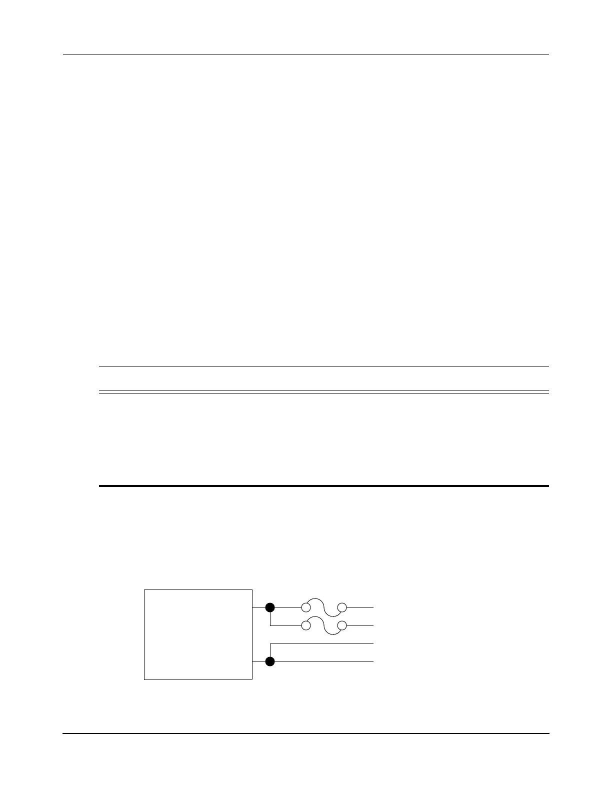
Supplies listed in Table 5-3, fusing must be provided for the power lines as shown in
Figure 5-17.
Figure 5-17: Fusing for Allen-Bradley Power Supplies
Table 5-3: Allen-Bradley Power Supplies
Product Description
1606-XLS480G Performance Power Supply, 36V DC, 480 W, 120/240V AC Input Voltage, see
Bulletin
1606 36V,13 A Single Phase Input--Power Supply, 1606-sr013
(10000051155)
1606-XLS480G-3 Performance Power Supply, 36V DC, 480 W, 3-Phase 480V AC wide range, see
Bulletin 1606 36V,13.3 A Three Phase Input--Power Supply,
1606-sr017
(10000051161)
V+
V-
250V AC (125V DC), 10 A ceramic slow blow fuses
(Littelfuse 326 or equivalent)
V+ Propulsion
V+ Logic
V- Logic
GND
1606-XLS480
Power Supply
 Loading...


