Design Guidelines
Transport System Options
128 MagneMotion
Rockwell Automation Publication MMI-UM002F-EN-P - October 2022
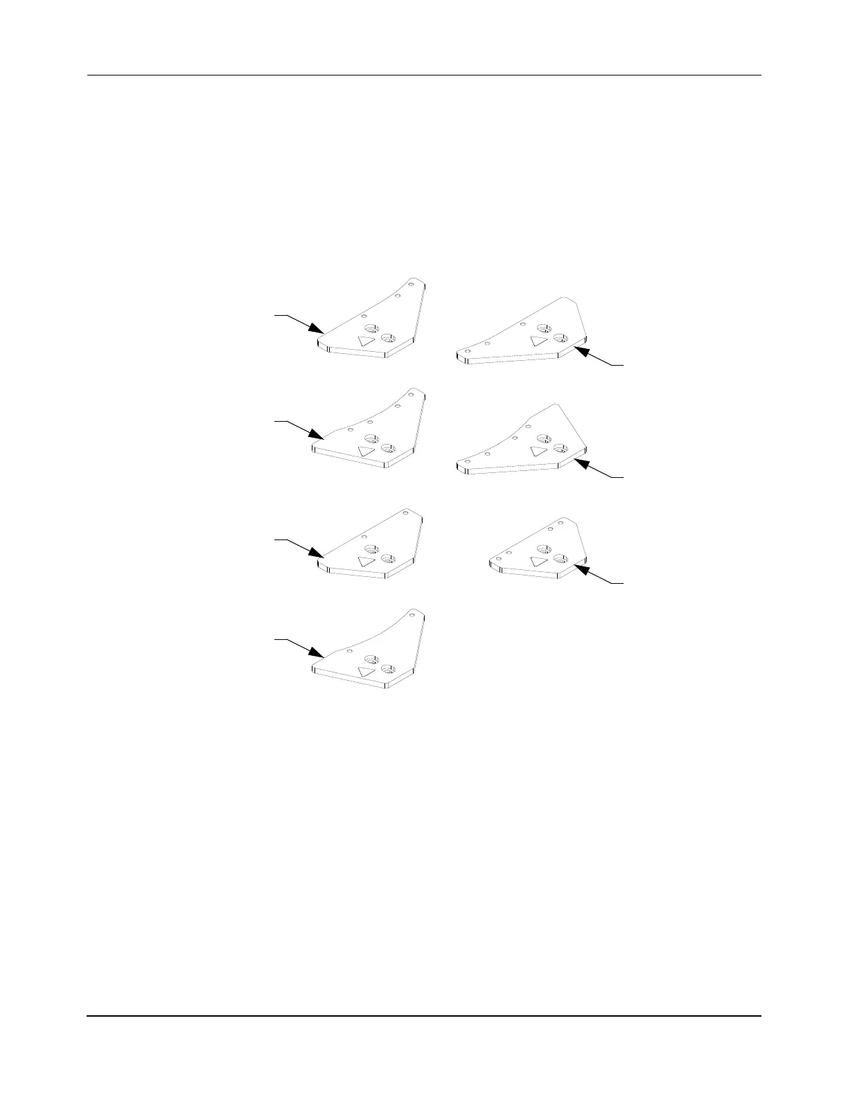
Spine Plates
Seven different spine plates, which are shown in Figure 3-53, are available for supporting and
connecting the rails within a precision rail system as shown in Figure 3-51 and Figure 3-52.
The spine plates attach directly to the top of the support post assemblies.
The type of joint (that is, curve-to-curve, curve-to-straight, straight-to-straight) determines the
type of spine plate required. Additional spine plates are provided to support the precision rails
in areas where there is no joint.
Figure 3-53: Precision Rail Spine Plates
Straight, No Joint
Straight to Curve
Left Joint
Curve to Curve
Left Joint
180º Curve
Straight to Curve
Right Joint
Curve to Curve
No Joint
Right Joint
Straight, Joint
 Loading...


