Design Guidelines
Transport System Design
MagneMover LITE User Manual 93
Rockwell Automation Publication MMI-UM002F-EN-P - October 2022
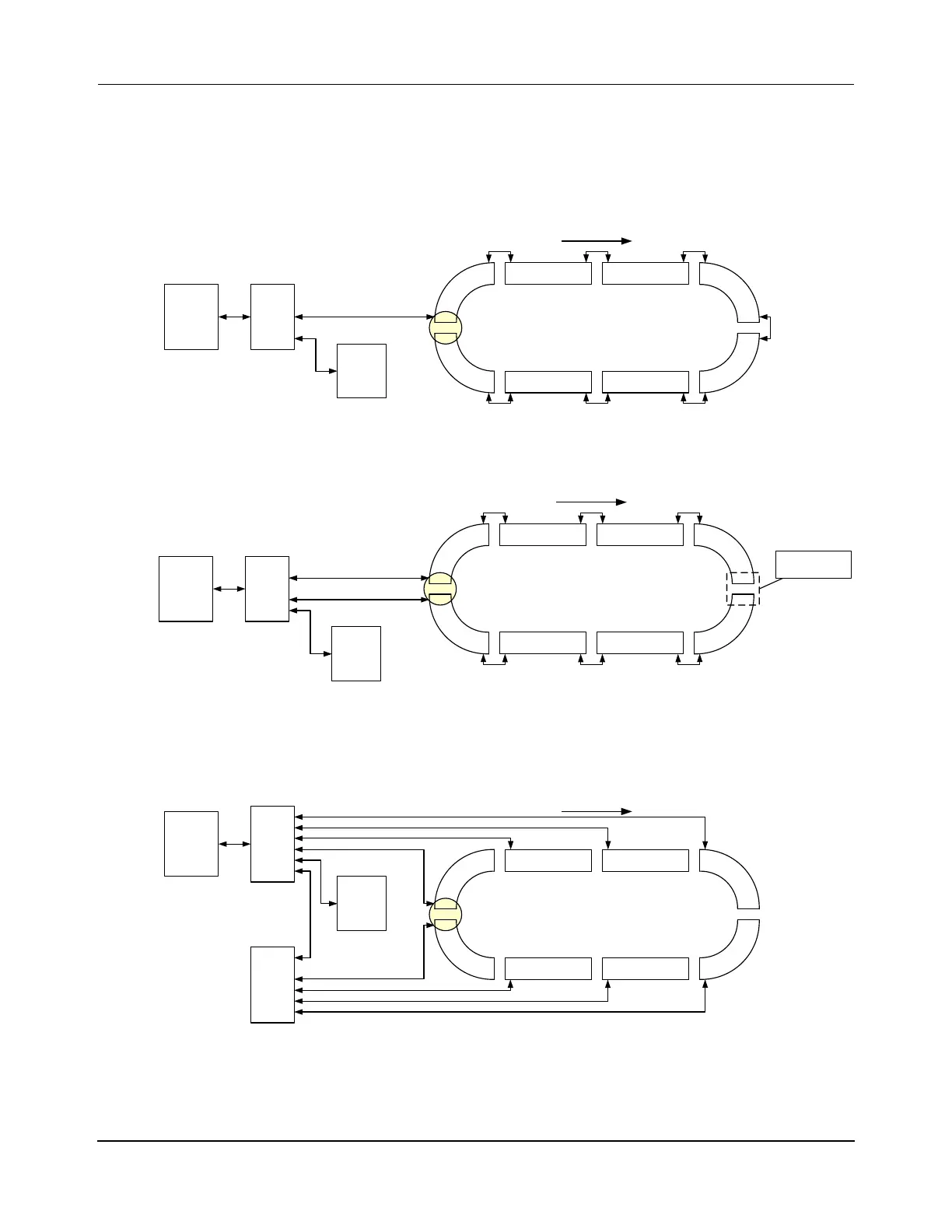
Loop Paths
The following figures show simplified connection diagrams of the different methods for con-
necting a loop of motors using Ethernet. The specific connection method that is used depends
on the application for the motors.
Figure 3-15: Ethernet Motor Wiring – One Path, One Ethernet Chain
Figure 3-16: Ethernet Motor Wiring – One Path, Two Ethernet Chains
Figure 3-17: Ethernet Motor Wiring – One Path, Ethernet Star
HLC &
Node
Controller
Host
Controller
Enet
Switch
Relay
Node
Enet Motor Enet Motor
Loop Transport System (Recommended):
One Enet Connection, One Chain
One Path
Enet Motor Enet Motor
x.y.0.10
P1M1
x.y.1.1
P1M2
x.y.1.2
P1M3
x.y.1.3
P1M4
x.y.1.4
P1M5
x.y.1.5
P1M6
x.y.1.6
P1M7
x.y.1.7
P1M8
x.y.1.8
Enet
Motor
Enet
Motor
Enet
Motor
Enet
Motor
Ethernet
Downstream
Relay
Node
HLC &
Node
Controller
Host
Controller
Enet
Switch
Loop Transport System:
One Enet Connection per Side, Split Chain
One Path
Chains must not
be connected
x.y.0.10
Enet Motor Enet Motor
Enet Motor Enet Motor
P1M1
x.y.1.1
P1M2
x.y.1.2
P1M3
x.y.1.3
P1M4
x.y.1.4
P1M5
x.y.1.5
P1M6
x.y.1.6
P1M7
x.y.1.7
P1M8
x.y.1.8
Enet
Motor
Enet
Motor
Enet
Motor
Enet
Motor
Ethernet
Downstream
HLC &
Node
Controller
Host
Controller
Enet
Switch
Loop Transport System:
One Enet Connection per Motor, Star Topology,
One Path
x.y.0.10
Relay
Node
Enet Motor Enet Motor
Enet Motor Enet Motor
P1M1
x.y.1.1
P1M2
x.y.1.2
P1M3
x.y.1.3
P1M4
x.y.1.4
P1M5
x.y.1.5
P1M6
x.y.1.6
P1M7
x.y.1.7
P1M8
x.y.1.8
Enet
Motor
Enet
Motor
Enet
Motor
Enet
Motor
Ethernet
Downstream
Enet
Switch
 Loading...


