Design Guidelines
Transport System Design
94 MagneMotion
Rockwell Automation Publication MMI-UM002F-EN-P - October 2022
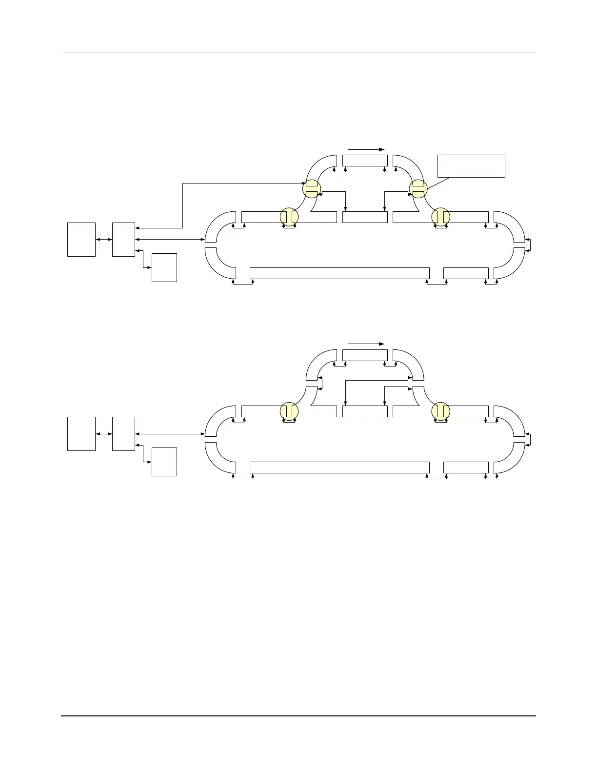
Multiple Paths
The following figures show simplified connection diagrams of the different methods for con-
necting a multiple-path transport system using Ethernet. The specific connection method that
is used depends on the application for the motors.
Figure 3-18: Ethernet Motor Wiring – Five Paths, Two Ethernet Chains, Main Loop and Spur
Figure 3-19: Ethernet Motor Wiring – Three Paths, One Ethernet Chain, Main Loop and Spur
Relay
Node
Relay
Node
Diverge
Node
Merge
Node
Enet Motor
HLC &
Node
Controller
Host
Controller
Enet
Switch
Enet Motor
Enet Motor Enet MotorEnet Motor
Enet Motor
Enet
Switch
Enet
Switch
Loop Transport System with Switches (Recommended):
One Enet Connection per Section (Main Loop & Spur), Split Chain
Five Paths
x.y.0.10
Use of Relay Nodes allows
spur to be offline whil e main
loop is running
P1M7
x.y.1.7
P1M2
x.y.1.2
P1M3
x.y.1.3
P1M6
x.y.1.6
Enet
Motor
Enet
Motor
Enet
Motor
Enet
Motor
P1M5
x.y.1.5
P1M4
x.y.1.4
P1M1
x.y.1.1
P1M8
x.y.1.8
P3M1
P2M1
x.y.2.1
P2M2
x.y.2.2
P5M1
P2M3
x.y.2.3
P4M1
x.y.4.1
Enet
Motor
P4M2
x.y.4.2
P4M3
x.y.4.3
Enet
Motor
Ethernet
Downstream
Diverge
Node
Merge
Node
Enet Motor
HLC &
Node
Controller
Host
Controller
Enet
Switch
Enet Motor
Enet Motor Enet MotorEnet Motor
Enet
Switch
Enet
Switch
Loop Transport System with Switches:
One Enet Connection, Single Chain
Three Paths
x.y.0.10
P1M5
x.y.1.5
P1M4
x.y.1.4
P1M1
x.y.1.1
P1M3
x.y.1.3
Enet
Motor
Enet
Motor
P1M2
x.y.1.2
Enet
Motor
Enet
Motor
P1M7
x.y.1.7
P1M6
x.y.1.6
P1M8
x.y.1.8
P2M2
x.y.2.2
P2M3
P3M5
x.y.2.3
P2M1
P3M1
x.y.2.1
Enet Motor
P3M2
x.y.3.2
Enet
Motor
P3M3
x.y.3.3
P3M4
x.y.3.4
Enet
Motor
Ethernet
Downstream
 Loading...


