Installation
Option Installation
290 MagneMotion
Rockwell Automation Publication MMI-UM002F-EN-P - October 2022
Curved Rail, No Joint Locations
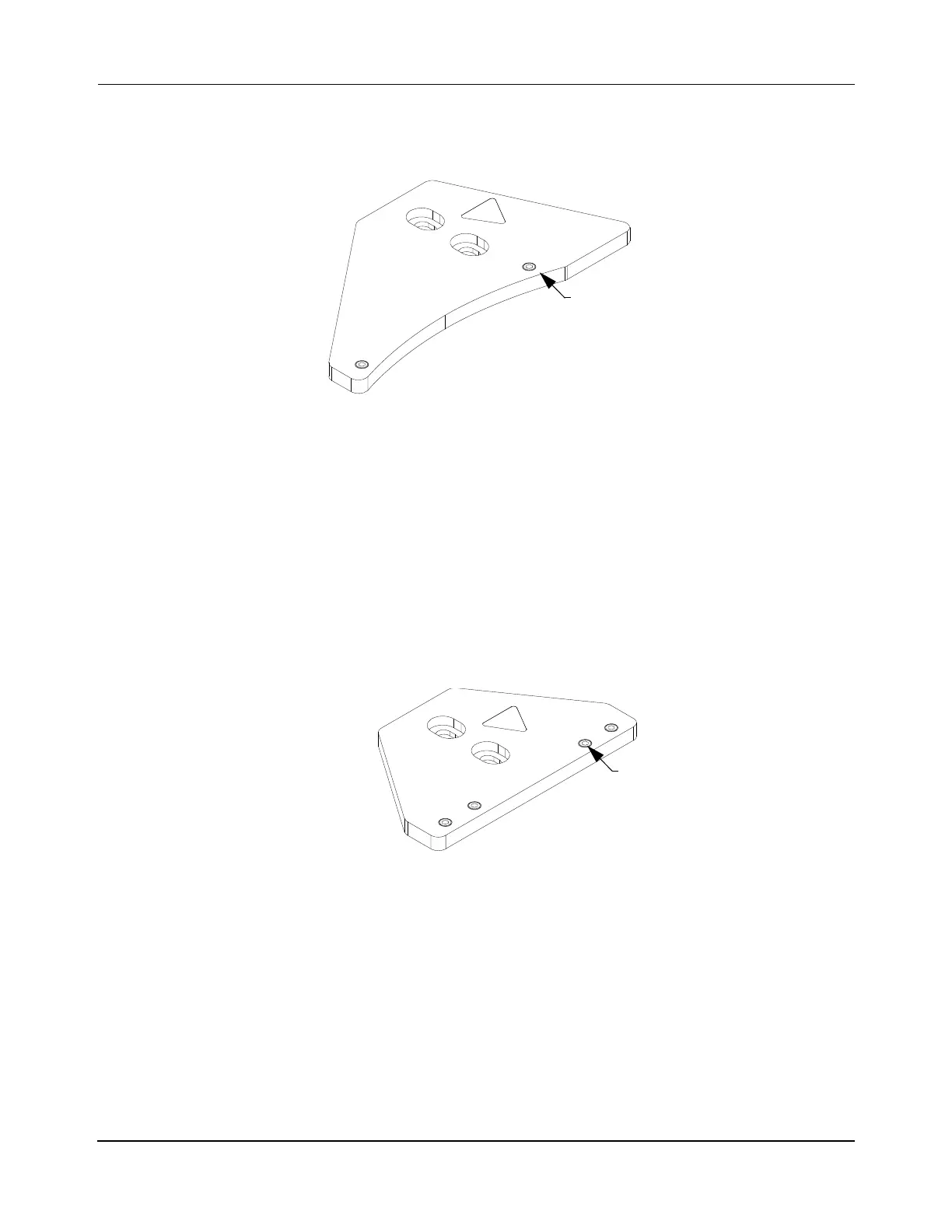
See Figure 5-38 when aligning and securing all 180° curved rails at mid-point locations.
Figure 5-38: Tightening Sequence, 180° Curve No Joint Precision Rail Spine Plate
1. Once the rail is aligned, tighten each screw to 1.8 N•m [16 in•lb] following the
sequence shown in Figure 5-38.
2. Repeat Step 1 for all 180° curved rails at the mid-point.
Straight, No Joint Locations
See Figure 5-39 when aligning and securing all straight rails at mid-point locations. For
greater stability, it is recommended that spine plates are located every 500 mm along straight
rail segments that are greater than 500 mm long.
Figure 5-39: Tightening Sequence, Straight Rail No-Joint Precision Rail Spine Plate
1. Once the rail is aligned, tighten each screw to 1.8 N•m [16 in•lb] following the
sequence shown in Figure 5-39.
2. Repeat Step 1 for all points on the rail.
3. Repeat Step 1 and Step 2 for all straight rail segments that are greater than 500 mm in
long.
 Loading...


