Design Guidelines
Transport System Layout
78 MagneMotion
Rockwell Automation Publication MMI-UM002F-EN-P - October 2022
Node Controllers
Once all paths and nodes have been identified on the MM LITE transport system layout, the
node controllers and their connections to the motors at the nodes must be defined. This defini-
tion typically includes identifying the type of node controllers being used (the example in
Figure 3-4 shows NC LITE node controllers with RS-422 motor communication being used).
Node controllers coordinate all motor operations and communicate with the high-level con-
troller (HLC). In all MM LITE transport systems, one node controller is designated as the
HLC. The HLC manages the communication between all node controllers in the transport sys-
tem and the host controller. See the Node Controller Hardware User Manual, MMI-UM013
for descriptions, specifications, and installation information for the different node controllers.
The node controller types that the MM LITE transport system supports are:
• NC-S Node Controller – Provides one active network port and eight RS-422 ports.
• NC-E Node Controller – Provides one active network port, four digital inputs, and
four digital outputs.
• NC-12 Node Controller – Provides one network port, 12 RS-422 ports, two RS-232
ports, 16 digital inputs, and 16 digital outputs.
• NC LITE Node Controller – Provides one network port and four RS-422 ports.
Motor Communication – Identifies the communication connections between motors on the
same path and between motors at path ends and the node controllers.
NOTE: All motor connections at a node must be made to the same node controller.
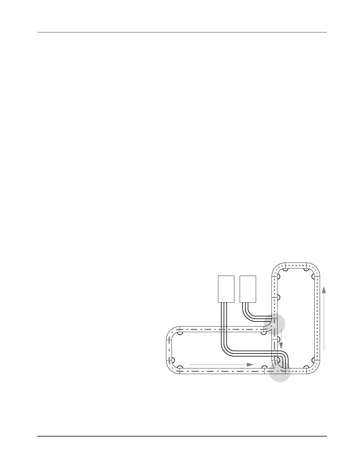
Figure 3-4: Sample MM LITE Transport System Layout Showing Node Controllers
3 1000 mm motor
6 250 mm motor
5 90° curve motor
2 Right switch
Qty Description
3 Paths
NC 1 NC 2
&
HLC
2 Nodes
1 Diverge
1 Merge
NOTE: Arrows indicate direction of forward motion.
Diverge
Merge
2 Node Controller LITEs (NCn)
 Loading...


