Maintenance
Repair
MagneMover LITE User Manual 405
Rockwell Automation Publication MMI-UM002F-EN-P - October 2022
C. Place the new protective strip on a flat surface with the adhesive side up and
remove the adhesive protective backing from the strip.
NOTE: If a PTFE protective strip was used, it is replaced with the new
UHMW protective strip.
D. Carefully center the magnet array over the center of the adhesive strip. Fold
both ends of the strip over the sides of the array. Then fold the holes at each
end of the strip over the threaded standoffs as shown in Figure 7-18.
NOTE: Do not stretch the protective strip. Stretching reduces the life of the
adhesive, which causes the strip to peel away from the array.
E. Press the strip into place. Use a burnisher and make sure that there are no bub-
bles.
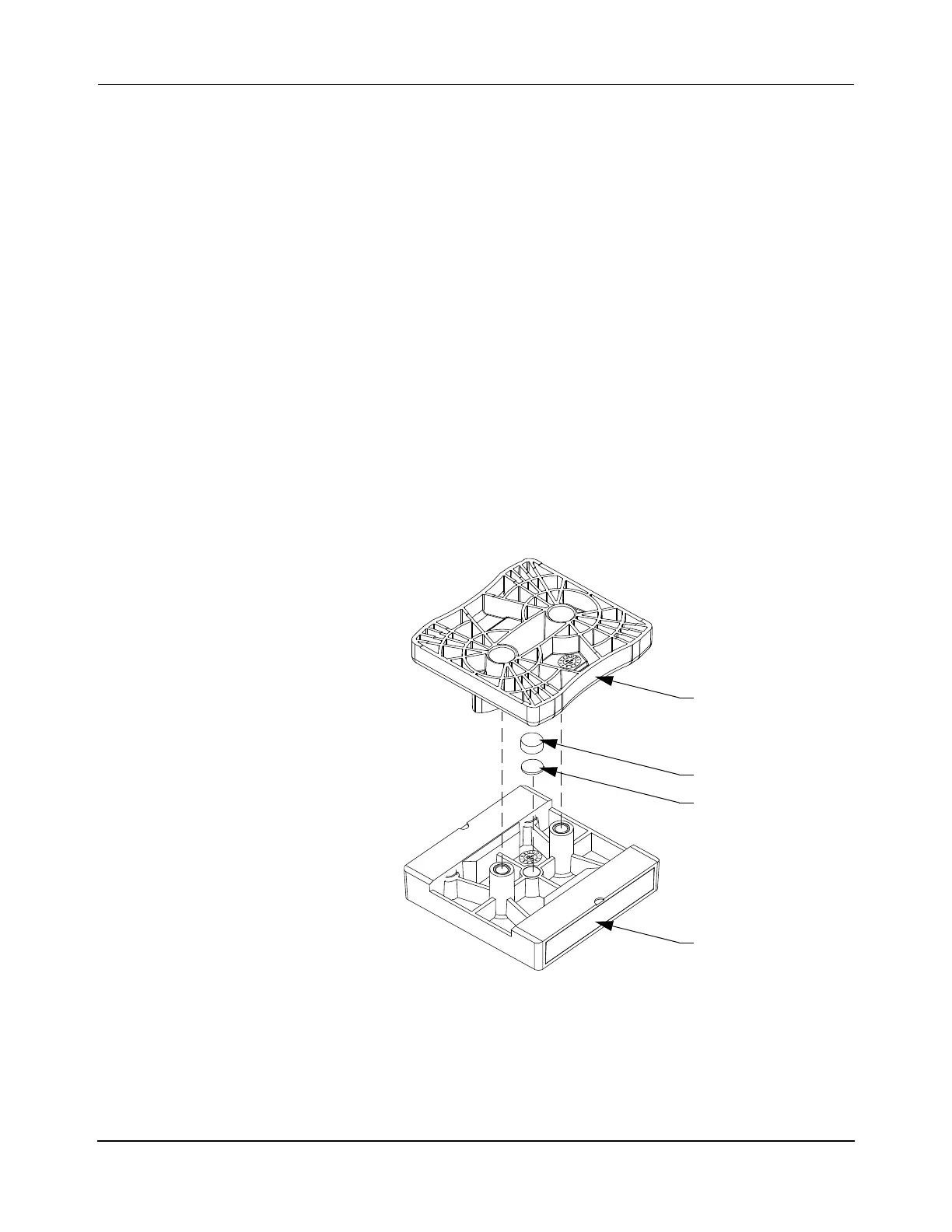
5. Remove the backing from the glue dot and apply the glue dot to the center surface of
the preload spacer as shown in Figure 7-19.
6. Locate the preload spacer on the center hole on the underside of the top plate, make
sure that the surface with the glue dot is fully seated and adhered to the top plate.
7. Align the top plate with the center plate and press together as shown in Figure 7-19.
Figure 7-19: Adhere Preload Spacer to Underside of Top Plate
8. Locate the plate assembly over the standoffs on the magnet assembly. Secure using
new M4 x 22 mm flat head screws with Dri-Loc and tighten to 1.5 N•m [13 in•lb].
The Loctite must cure for 2 hours at 22° C [72° F] before using the puck.
9. Replace the puck on the MM LITE transport system (see Replace Pucks on page 399).
Center Plate
Compliant Spacer
Glue Dot
Top Plate
 Loading...


