Installation
Option Installation
300 MagneMotion
Rockwell Automation Publication MMI-UM002F-EN-P - October 2022
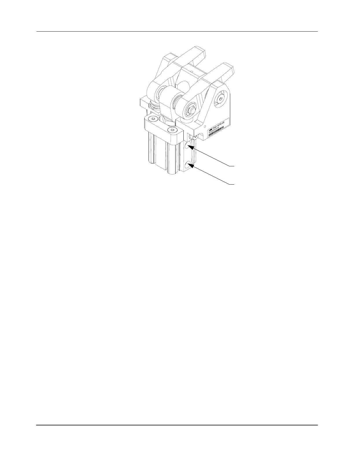
Figure 5-45: Precision Locator Pneumatic Connections
1. Install the pneumatic valve to control the precision locator. This procedure assumes
the use of a 5/2 valve as described in Precision Locator Installation on page 137. Typ-
ically, 6 mm OD tubing is used.
A. Connect the pneumatic valve control lines to the digital I/O on the host control-
ler.
B. Connect the pneumatic input for the valve to the facility compressed air.
C. Connect the #2 output from the pneumatic valve to the Open Locator fitting on
the pneumatic cylinder.
D. Connect the #4 output from the pneumatic valve to Close Locator fitting on the
pneumatic cylinder.
E. Connect the exhaust #3 output from the pneumatic valve to a flow control
valve. Adjust the flow control valve to limit the pinning time to 100 ms or
greater. All life estimates are based on a pinning time of at least 100 ms.
F. Connect the exhaust #5 output from the pneumatic valve to a muffler.
2. If the optional cylinder position sensors are being used:
• If user-supplied sensors are being installed, position and secure them as
directed by the manufacturer.
• If the sensors are installed, verify that they are in the correct positions and
adjust if necessary. To adjust, loosen the 2.5 mm set screw, adjust the position
of the sensor, and tighten the set screw.
Open Locator
Close Locator
(Extend Cylinder)
(Retract Cylinder)
 Loading...


