Installation
Transport System Installation
248 MagneMotion
Rockwell Automation Publication MMI-UM002F-EN-P - October 2022
Installing System Legs
Once the beam sections are assembled, the legs must be attached.
1. Invert the beam and place on a clean work surface.
NOTE: Make sure that the beam is inverted as some sections have an orientation and
must be installed correctly to enable mounting of the motors.
2. Attach the single path legs at the appropriate locations (if not already installed) as
shown in Figure 5-2.
NOTE: Orient the feet as required to allow proper final installation of the beam.
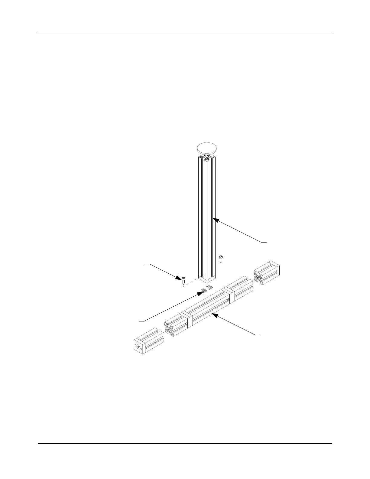
Figure 5-2: Leg on a Single Path Beam Assembly
A. Insert two M8 T-nuts and rotate into position in the channel on the bottom of
the beam at the position for the leg. T-nuts must be inserted so that the spring
steel tabs are facing toward the beam, then rotated clockwise into place.
B. Position the leg over the T-nuts, apply Loctite 243 to two M8 x 25 mm screws.
Install and tighten the screws to 26 N•m [230 in•lb] with a 6 mm Hex bit.
The Loctite must cure for 2 hours at 22° C [72° F] before using the transport
system.
Leg Stand Assembly
Beam
M8 T-Nut
(2X)
M8 x 25 mm Screw
(2X)
 Loading...


