Design Guidelines
Transport System Design
MagneMover LITE User Manual 91
Rockwell Automation Publication MMI-UM002F-EN-P - October 2022
• The use of Allen-Bradley
®
Stratix
®
Managed Ethernet Switches is recommended to
deliver the required network performance.
• Ethernet chains can consist of multiple paths (as defined in the transport system layout
drawing).
• Chains do not need to start at the beginning of a path.
• If all motors in a path are not part of the same Ethernet chain, all chains the path is a
member of must connect to the same network as the node controller.
Ethernet Motor Connection Examples
The MagneMover LITE Ethernet motors, which use Ethernet for motor to motor communica-
tion and for motor to node controller communication can use different network topologies
depending on the application. When using Ethernet, all motors in a specific path must be on
the same network as the node controller (see Figure 3-10 through Figure 3-22). Additionally,
all motors and their location in the transport system must be defined in the MICS file (see
Ethernet Motor MICS File on page 97).
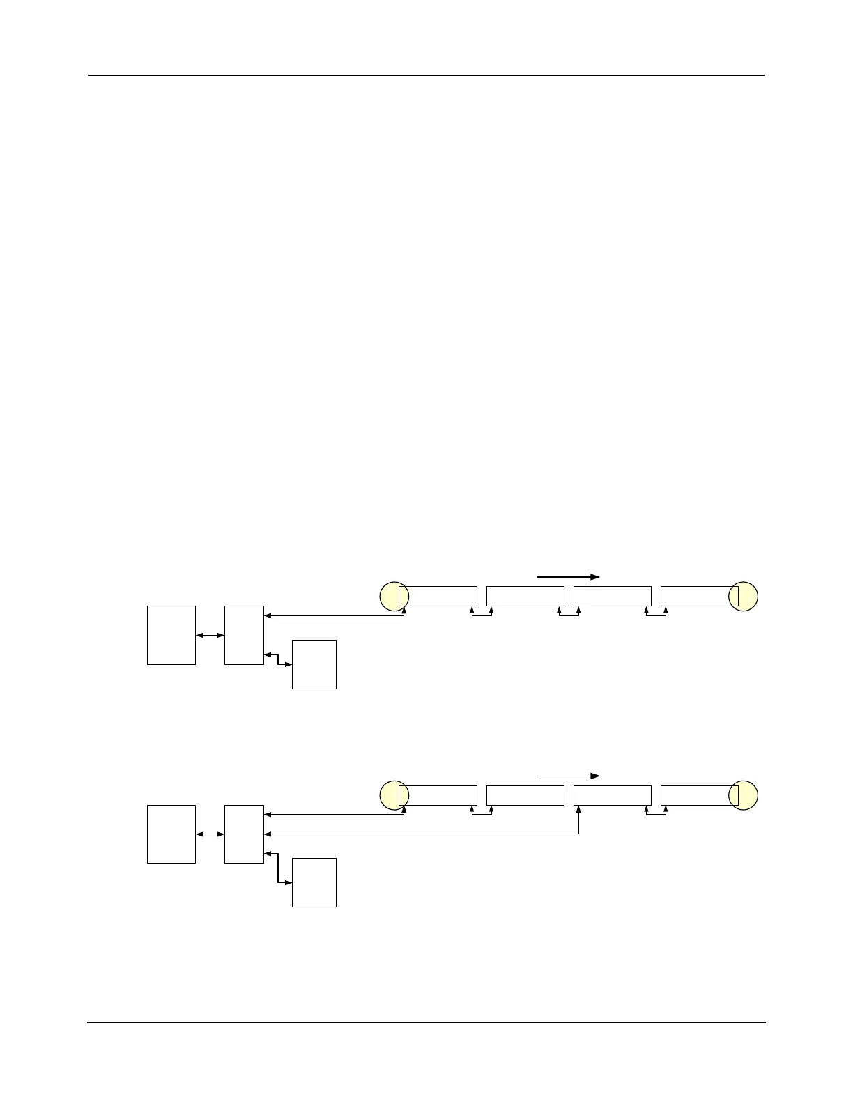
Straight Paths
The following figures show simplified connection diagrams of the different methods for con-
necting a simple string of motors using Ethernet. The specific connection method that is used
depends on the application for the motors.
Figure 3-10: Ethernet Motor Wiring – One Path, One Ethernet Chain
Figure 3-11: Ethernet Motor Wiring – One Path, Two Ethernet Chains
Term
Node
Simple
Node
Enet Motor
Host
Controller
Enet Motor Enet Motor Enet Motor
Enet
Switch
HLC &
Node
Controller
Straight Transport System (recommended):
One Enet Connection per Chain, One Chain,
One Path
x.y.0.10
P1M1
x.y.1.1
P1M2
x.y.1.2
P1M3
x.y.1.3
P1M4
x.y.1.4
Ethernet
Downstream
Term
Node
Simple
Node
Enet Motor
Host
Controller
Enet Motor Enet Motor Enet Motor
Enet
Switch
HLC &
Node
Controller
Straight Transport System:
One Enet Connection per Chain, Split Chain,
One Path
x.y.0.10
P1M1
x.y.1.1
P1M2
x.y.1.2
P1M3
x.y.1.3
P1M4
x.y.1.4
Ethernet
Downstream
 Loading...


